<< Chapter < Page Chapter >> Page >
By the end of the section, you will be able to:
  • Interpret phasor diagrams and apply them to ac circuits with resistors, capacitors, and inductors
  • Define the reactance for a resistor, capacitor, and inductor to help understand how current in the circuit behaves compared to each of these devices

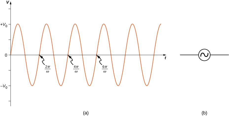
In this section, we study simple models of ac voltage sources connected to three circuit components: (1) a resistor, (2) a capacitor, and (3) an inductor. The power furnished by an ac voltage source has an emf given by

v ( t ) = V 0 sin ω t ,

as shown in [link] . This sine function assumes we start recording the voltage when it is v = 0 V at a time of t = 0 s . A phase constant may be involved that shifts the function when we start measuring voltages, similar to the phase constant in the waves we studied in Waves . However, because we are free to choose when we start examining the voltage, we can ignore this phase constant for now. We can measure this voltage across the circuit components using one of two methods: (1) a quantitative approach based on our knowledge of circuits, or (2) a graphical approach that is explained in the coming sections.

Figure shows a sine wave with maximum and minimum values of the voltage being V0 and minus V0 respectively. Each positive slope of the wave, at the x-axis, marks one complete wavelength. These points are labeled in sequence: 2 pi by omega, 4 pi by omega and 6 pi by omega.
(a) The output v ( t ) = V 0 sin ω t of an ac generator. (b) Symbol used to represent an ac voltage source in a circuit diagram.

Resistor

First, consider a resistor connected across an ac voltage source. From Kirchhoff’s loop rule, the instantaneous voltage across the resistor of [link] (a) is

v R ( t ) = V 0 sin ω t

and the instantaneous current through the resistor is
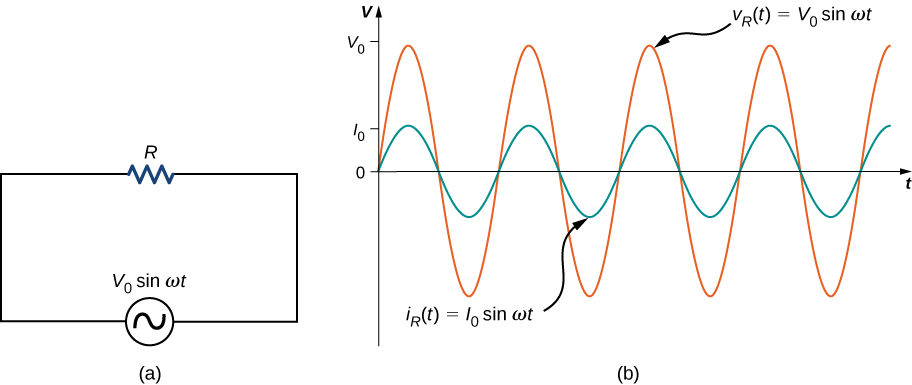
i R ( t ) = v R ( t ) R = V 0 R sin ω t = I 0 sin ω t .
Figure a shows a circuit with an AC voltage source connected to a resistor. The source is labeled V0 sine omega t. Figure b shows sine waves of AC voltage and current on the same graph. Voltage has a greater amplitude than current and its maximum value is marked V0 on the y axis. The maximum value of current is marked I0. The voltage curve is labeled V subscript R parentheses t parentheses equal to V0 sine omega t. The current curve is labeled I subscript R parentheses t parentheses equal to I0 sine omega t.
(a) A resistor connected across an ac voltage source. (b) The current i R ( t ) through the resistor and the voltage v R ( t ) across the resistor. The two quantities are in phase.

Here, I 0 = V 0 / R is the amplitude of the time-varying current. Plots of i R ( t ) and v R ( t ) are shown in [link] (b). Both curves reach their maxima and minima at the same times, that is, the current through and the voltage across the resistor are in phase.

Graphical representations of the phase relationships between current and voltage are often useful in the analysis of ac circuits. Such representations are called phasor diagrams . The phasor diagram for i R ( t ) is shown in [link] (a), with the current on the vertical axis. The arrow (or phasor) is rotating counterclockwise at a constant angular frequency ω , so we are viewing it at one instant in time. If the length of the arrow corresponds to the current amplitude I 0 , the projection of the rotating arrow onto the vertical axis is i R ( t ) = I 0 sin ω t , which is the instantaneous current.

Figure shows the coordinate axes. An arrow labeled V0 starts from the origin and points up and right making an angle omega t with the x axis. An arrow labeled omega is shown near its tip, perpendicular to it, pointing up and left. The tip of the arrow V0 makes a y-intercept labeled V subscript C parentheses t parentheses. An arrow labeled I0 starts at the origin and points up and left. It is perpendicular to V0. It makes a y intercept labeled i subscript C parentheses t parentheses. A arrow labeled omega is shown near its tip, perpendicular to it, pointing down and left.
(a) The phasor diagram representing the current through the resistor of [link] . (b) The phasor diagram representing both i R ( t ) and v R ( t ) .

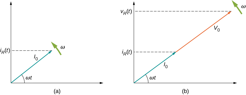
The vertical axis on a phasor diagram could be either the voltage or the current, depending on the phasor that is being examined. In addition, several quantities can be depicted on the same phasor diagram. For example, both the current i R ( t ) and the voltage v R ( t ) are shown in the diagram of [link] (b). Since they have the same frequency and are in phase, their phasors point in the same direction and rotate together. The relative lengths of the two phasors are arbitrary because they represent different quantities; however, the ratio of the lengths of the two phasors can be represented by the resistance, since one is a voltage phasor and the other is a current phasor.

Questions & Answers

what is biology
Hajah Reply
the study of living organisms and their interactions with one another and their environments
AI-Robot
what is biology
Victoria Reply
HOW CAN MAN ORGAN FUNCTION
Alfred Reply
the diagram of the digestive system
Assiatu Reply
allimentary cannel
Ogenrwot
How does twins formed
William Reply
They formed in two ways first when one sperm and one egg are splited by mitosis or two sperm and two eggs join together
Oluwatobi
what is genetics
Josephine Reply
Genetics is the study of heredity
Misack
how does twins formed?
Misack
What is manual
Hassan Reply
discuss biological phenomenon and provide pieces of evidence to show that it was responsible for the formation of eukaryotic organelles
Joseph Reply
what is biology
Yousuf Reply
the study of living organisms and their interactions with one another and their environment.
Wine
discuss the biological phenomenon and provide pieces of evidence to show that it was responsible for the formation of eukaryotic organelles in an essay form
Joseph Reply
what is the blood cells
Shaker Reply
list any five characteristics of the blood cells
Shaker
lack electricity and its more savely than electronic microscope because its naturally by using of light
Abdullahi Reply
advantage of electronic microscope is easily and clearly while disadvantage is dangerous because its electronic. advantage of light microscope is savely and naturally by sun while disadvantage is not easily,means its not sharp and not clear
Abdullahi
cell theory state that every organisms composed of one or more cell,cell is the basic unit of life
Abdullahi
is like gone fail us
DENG
cells is the basic structure and functions of all living things
Ramadan
What is classification
ISCONT Reply
is organisms that are similar into groups called tara
Yamosa
in what situation (s) would be the use of a scanning electron microscope be ideal and why?
Kenna Reply
A scanning electron microscope (SEM) is ideal for situations requiring high-resolution imaging of surfaces. It is commonly used in materials science, biology, and geology to examine the topography and composition of samples at a nanoscale level. SEM is particularly useful for studying fine details,
Hilary
cell is the building block of life.
Condoleezza Reply
Got questions? Join the online conversation and get instant answers!
Jobilize.com Reply
Practice Key Terms 4

Get Jobilize Job Search Mobile App in your pocket Now!

Get it on Google Play Download on the App Store Now


Source:  OpenStax, University physics volume 2. OpenStax CNX. Oct 06, 2016 Download for free at http://cnx.org/content/col12074/1.3
Google Play and the Google Play logo are trademarks of Google Inc.

Notification Switch

Would you like to follow the 'University physics volume 2' conversation and receive update notifications?

Ask