<< Chapter < Page Chapter >> Page >
I rms = I 0 2 ,

where I 0 is the peak current in an ac system. The rms voltage    , or the root mean square of the voltage, is

V rms = V 0 2 ,

where V 0 is the peak voltage in an ac system. The rms current appears because the voltage is continually reversing, charging, and discharging the capacitor. If the frequency goes to zero, which would be a dc voltage, X C tends to infinity, and the current is zero once the capacitor is charged. At very high frequencies, the capacitor’s reactance tends to zero—it has a negligible reactance and does not impede the current (it acts like a simple wire).

Inductor

Lastly, let’s consider an inductor    connected to an ac voltage source. From Kirchhoff’s loop rule, the voltage across the inductor L of [link] (a) is

v L ( t ) = V 0 sin ω t .

The emf across an inductor is equal to ε = L ( d i L / d t ) ; however, the potential difference across the inductor is v L ( t ) = L d i L ( t ) / d t , because if we consider that the voltage around the loop must equal zero, the voltage gained from the ac source must dissipate through the inductor. Therefore, connecting this with the ac voltage source, we have
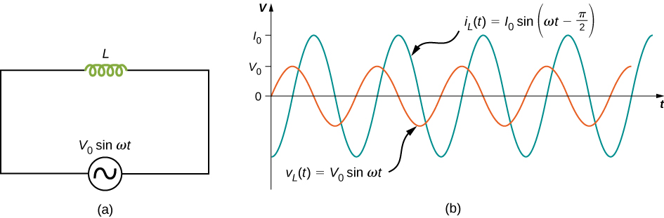
d i L ( t ) d t = V 0 L sin ω t .
Figure a shows a circuit with an AC voltage source connected to an inductor. The source is labeled V0 sine omega t. Figure b shows sine waves of AC voltage and current on the same graph. Voltage has a smaller amplitude than current and its maximum value is marked V0 on the y axis. The maximum value of current is marked I0. The two curves have the same wavelength but are out of phase by one quarter wavelength. The voltage curve is labeled V subscript L parentheses t parentheses equal to V0 sine omega t. The current curve is labeled I subscript L parentheses t parentheses equal to I0 sine parentheses omega t minus pi by 2 parentheses.
(a) An inductor connected across an ac generator. (b) The current i L ( t ) through the inductor and the voltage v L ( t ) across the inductor. Here i L ( t ) lags v L ( t ) by π / 2 rad.

The current i L ( t ) is found by integrating this equation. Since the circuit does not contain a source of constant emf, there is no steady current in the circuit. Hence, we can set the constant of integration, which represents the steady current in the circuit, equal to zero, and we have

i L ( t ) = V 0 ω L cos ω t = V 0 ω L sin ( ω t π 2 ) = I 0 sin ( ω t π 2 ) ,

where I 0 = V 0 / ω L . The relationship between V 0 and I 0 may also be written in a form analogous to Ohm’s law:

V 0 I 0 = ω L = X L .

The quantity X L is known as the inductive reactance    of the inductor, or the opposition of an inductor to a change in current; its unit is also the ohm. Note that X L varies directly as the frequency of the ac source—high frequency causes high inductive reactance.
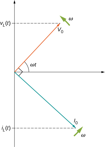
A phase difference of π / 2 rad occurs between the current through and the voltage across the inductor. From [link] and [link] , the current through an inductor lags the potential difference across an inductor by π / 2 rad , or a quarter of a cycle. The phasor diagram for this case is shown in [link] .

Figure shows the coordinate axes. An arrow labeled V0 starts from the origin and points up and right making an angle omega t with the x axis. An arrow labeled omega is shown near its tip, perpendicular to it, pointing up and left. The tip of the arrow V0 makes a y-intercept labeled V subscript L parentheses t parentheses. An arrow labeled I0 starts at the origin and points down and right. It is perpendicular to V0. Its intercept on the negative y-axis is labeled i subscript L parentheses t parentheses. A arrow labeled omega is shown near its tip, perpendicular to it, pointing up and right.
The phasor diagram for the inductor of [link] . The current phasor lags the voltage phasor by π / 2 rad as they both rotate with the same angular frequency.

An animation from the University of New South Wales AC Circuits illustrates some of the concepts we discuss in this chapter. They also include wave and phasor diagrams that evolve over time so that you can get a better picture of how each changes over time.

Simple ac circuits

An ac generator produces an emf of amplitude 10 V at a frequency f = 60 Hz . Determine the voltages across and the currents through the circuit elements when the generator is connected to (a) a 100 - Ω resistor, (b) a 10 - μ F capacitor, and (c) a 15-mH inductor.

Strategy

The entire AC voltage across each device is the same as the source voltage. We can find the currents by finding the reactance X of each device and solving for the peak current using I 0 = V 0 / X .

Solution

The voltage across the terminals of the source is

v ( t ) = V 0 sin ω t = ( 10 V ) sin 120 π t ,

where ω = 2 π f = 120 π rad/s is the angular frequency. Since v ( t ) is also the voltage across each of the elements, we have

v ( t ) = v R ( t ) = v C ( t ) = v L ( t ) = ( 10 V ) sin 120 π t .

a. When R = 100 Ω , the amplitude of the current through the resistor is

I 0 = V 0 / R = 10 V / 100 Ω = 0.10 A,

so

i R ( t ) = ( 0.10 A ) sin 120 π t .

b. From [link] , the capacitive reactance is

X C = 1 ω C = 1 ( 120 π rad/s ) ( 10 × 10 −6 F ) = 265 Ω ,

so the maximum value of the current is

I 0 = V 0 X C = 10 V 265 Ω = 3.8 × 10 −2 A

and the instantaneous current is given by

i C ( t ) = ( 3.8 × 10 −2 A ) sin ( 120 π t + π 2 ) .

c. From [link] , the inductive reactance is

X L = ω L = ( 120 π rad/s ) ( 15 × 10 −3 H ) = 5.7 Ω .

The maximum current is therefore

I 0 = 10 V 5.7 Ω = 1.8 A

and the instantaneous current is

i L ( t ) = ( 1.8 A ) sin ( 120 π t π 2 ) .

Significance

Although the voltage across each device is the same, the peak current has different values, depending on the reactance. The reactance for each device depends on the values of resistance, capacitance, or inductance.

Got questions? Get instant answers now!

Check Your Understanding Repeat [link] for an ac source of amplitude 20 V and frequency 100 Hz.

a. ( 20 V ) sin 200 π t , ( 0.20 A ) sin 200 π t ; b. ( 20 V ) sin 200 π t , ( 0.13 A ) sin ( 200 π t + π / 2 ) ; c. ( 20 V ) sin 200 π t , ( 2.1 A ) sin ( 200 π t π / 2 )

Got questions? Get instant answers now!

Summary

  • For resistors, the current through and the voltage across are in phase.
  • For capacitors, we find that when a sinusoidal voltage is applied to a capacitor, the voltage follows the current by one-fourth of a cycle. Since a capacitor can stop current when fully charged, it limits current and offers another form of ac resistance, called capacitive reactance, which has units of ohms.
  • For inductors in ac circuits, we find that when a sinusoidal voltage is applied to an inductor, the voltage leads the current by one-fourth of a cycle.
  • The opposition of an inductor to a change in current is expressed as a type of ac reactance. This inductive reactance, which has units of ohms, varies with the frequency of the ac source.

Conceptual questions

Explain why at high frequencies a capacitor acts as an ac short, whereas an inductor acts as an open circuit.

Got questions? Get instant answers now!

Problems

Calculate the reactance of a 5.0 - μ F capacitor at (a) 60 Hz, (b) 600 Hz, and (c) 6000 Hz.

a. 530 Ω ; b. 53 Ω ; c. 5.3 Ω

Got questions? Get instant answers now!

What is the capacitance of a capacitor whose reactance is 10 Ω at 60 Hz?

Got questions? Get instant answers now!

Calculate the reactance of a 5.0-mH inductor at (a) 60 Hz, (b) 600 Hz, and (c) 6000 Hz.

a. 1.9 Ω ; b. 19 Ω ; c. 190 Ω

Got questions? Get instant answers now!

What is the self-inductance of a coil whose reactance is 10 Ω at 60 Hz?

Got questions? Get instant answers now!

At what frequency is the reactance of a 20 - μ F capacitor equal to that of a 10-mH inductor?

360 Hz

Got questions? Get instant answers now!

At 1000 Hz, the reactance of a 5.0-mH inductor is equal to the reactance of a particular capacitor. What is the capacitance of the capacitor?

Got questions? Get instant answers now!

A 50 - Ω resistor is connected across the emf v ( t ) = ( 160 V ) sin ( 120 π t ) . Write an expression for the current through the resistor.

i ( t ) = ( 3.2 A ) sin ( 120 π t )

Got questions? Get instant answers now!

A 25 - μ F capacitor is connected to an emf given by v ( t ) = ( 160 V ) sin ( 120 π t ) . (a) What is the reactance of the capacitor? (b) Write an expression for the current output of the source.

Got questions? Get instant answers now!

A 100-mH inductor is connected across the emf of the preceding problem. (a) What is the reactance of the inductor? (b) Write an expression for the current through the inductor.

a. 38 Ω ; b. i ( t ) = ( 4.24 A ) sin ( 120 π t π / 2 )

Got questions? Get instant answers now!
Practice Key Terms 4

Get Jobilize Job Search Mobile App in your pocket Now!

Get it on Google Play Download on the App Store Now


Source:  OpenStax, University physics volume 2. OpenStax CNX. Oct 06, 2016 Download for free at http://cnx.org/content/col12074/1.3
Google Play and the Google Play logo are trademarks of Google Inc.

Notification Switch

Would you like to follow the 'University physics volume 2' conversation and receive update notifications?

Ask