<< Chapter < Page Chapter >> Page >
Figure a shows two people pushing a third using forces F1 and F2, which are perpendicular to each other. Another figure shows vector addition, where F1 and F2 are placed head to tail, and the resultant vector F total forms the hypotenuse of the triangle. Figure b shows a free body diagram where F1 and F2 originate from the same point source.
(a) An overhead view of two ice skaters pushing on a third skater. Forces are vectors and add like other vectors, so the total force on the third skater is in the direction shown. (b) A free-body diagram representing the forces acting on the third skater.

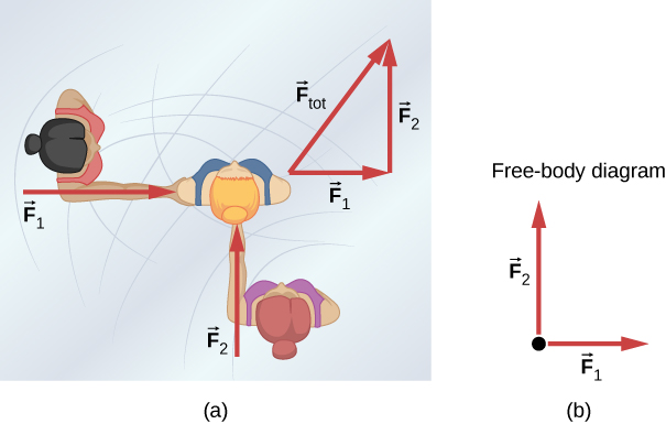
[link] (b) is our first example of a free-body diagram    , which is a sketch showing all external forces acting on an object or system. The object or system is represented by a single isolated point (or free body), and only those forces acting on it that originate outside of the object or system—that is, external force     s —are shown. (These forces are the only ones shown because only external forces acting on the free body affect its motion. We can ignore any internal forces within the body.) The forces are represented by vectors extending outward from the free body.

Free-body diagrams are useful in analyzing forces acting on an object or system, and are employed extensively in the study and application of Newton’s laws of motion. You will see them throughout this text and in all your studies of physics. The following steps briefly explain how a free-body diagram is created; we examine this strategy in more detail in Drawing Free-Body Diagrams .

Problem-solving strategy: drawing free-body diagrams

  1. Draw the object under consideration. If you are treating the object as a particle, represent the object as a point. Place this point at the origin of an xy -coordinate system.
  2. Include all forces that act on the object, representing these forces as vectors. However, do not include the net force on the object or the forces that the object exerts on its environment.
  3. Resolve all force vectors into x - and y -components.
  4. Draw a separate free-body diagram for each object in the problem.

We illustrate this strategy with two examples of free-body diagrams ( [link] ). The terms used in this figure are explained in more detail later in the chapter.

Figure a shows a box at rest on a horizontal surface. A free body diagram shows normal force vector pointing upwards and weight vector pointing downwards. Figure b shows a box on an inclined plane. Its free body diagram shows the weight vector pointing straight downwards, normal force vector pointing up, in a direction perpendicular to the plane and a friction force vector pointing up along the direction of the plane.
In these free-body diagrams, N is the normal force, w is the weight of the object, and f is the friction.

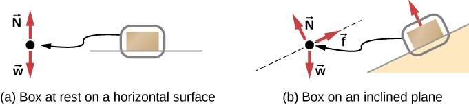
The steps given here are sufficient to guide you in this important problem-solving strategy. The final section of this chapter explains in more detail how to draw free-body diagrams when working with the ideas presented in this chapter.

Development of the force concept

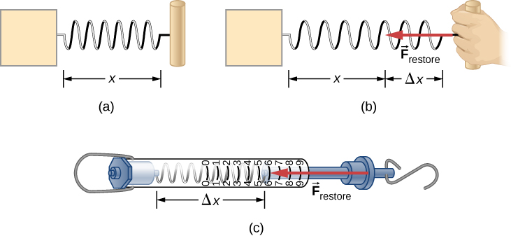
A quantitative definition of force can be based on some standard force, just as distance is measured in units relative to a standard length. One possibility is to stretch a spring a certain fixed distance ( [link] ) and use the force it exerts to pull itself back to its relaxed shape—called a restoring force —as a standard. The magnitude of all other forces can be considered as multiples of this standard unit of force. Many other possibilities exist for standard forces. Some alternative definitions of force will be given later in this chapter.

Figure a shows an undisturbed string of length x. Figure b shows the spring stretched by a distance delta x and a force F restore acting in the opposite direction. Figure c shows a spring scale. A hook attached to a spring is pulled in one direction. There are markings on the scale to show how much the spring has been stretched.
The force exerted by a stretched spring can be used as a standard unit of force. (a) This spring has a length x when undistorted. (b) When stretched a distance Δ x , the spring exerts a restoring force F restore , which is reproducible. (c) A spring scale is one device that uses a spring to measure force. The force F restore is exerted on whatever is attached to the hook. Here, this force has a magnitude of six units of the force standard being employed.
Practice Key Terms 6

Get Jobilize Job Search Mobile App in your pocket Now!

Get it on Google Play Download on the App Store Now


Source:  OpenStax, University physics volume 1. OpenStax CNX. Sep 19, 2016 Download for free at http://cnx.org/content/col12031/1.5
Google Play and the Google Play logo are trademarks of Google Inc.

Notification Switch

Would you like to follow the 'University physics volume 1' conversation and receive update notifications?

Ask