

| << Chapter < Page | Chapter >> Page > |
Combining [link] , [link] , and [link] , we find that L is given by
where is given by
and is the required SNR performance in dB. Note that when C is a large fraction of N , which is usually the case, the pulse response duration L actually grows faster than proportionally to the number of bins N .
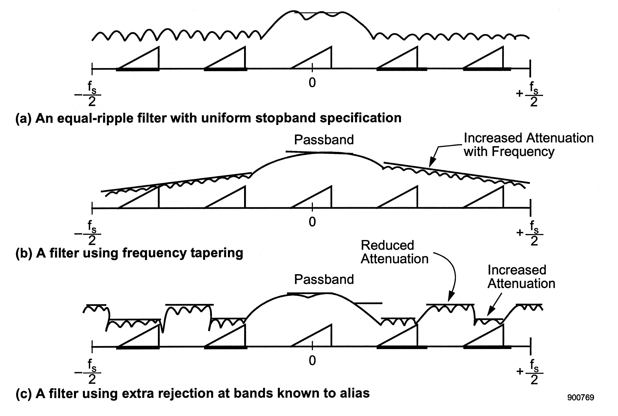
A warning is in order here. While accurate in principle and generally accurate numerically, this section presents a simplified view of the filter optimization problem and the implications of each of the technical requirements. Each actual application requires a careful evaluation of the specifications appropriate to it and the impact to each of the transmultiplexer's design parameters. In addition, note that we used [link] to reach some of these conclusions when, in fact, [link] is really the right one to use. To illustrate how this might affect the resulting design, observe that [link] implicitly assumes a pulse response of the type shown in [link] , which suppresses all channels not of interest about equally. Consider then the frequency responses shown in [link] . The first is a standard Parks-McClellan design in which the stopband ripple objective is the same over the whole stopband. The second two are alternative designs that use similar or less amounts of computation. The one shown in [link] (b) slowly increases the stopband suppression with higher frequency, essentially removing those channels from the SNR calculation. Another scheme, shown in [link] (c), obtains added suppression in the bands known to alias into the band of interest by releasing control in the bands that will not alias in. In passing, it should be noted that the Parks-McClellan software package can be modified to perform both of these filter designs. To summarize, the equations presented in this section serve as a good guide to the selection of the pulse response and its duration L , but skillful use of [link] and the full design formulas for FIR linear phase filters can reduce L and the implied required real-time computation level by 10 to 40%.
Several of the examples presented in The Impact of Digital Tuning on the Overall design of an FDM-TDM Transmux concern the use of FDM-TDM transmultiplexers to demultiplex the voice channels found in an FDM telephone baseband. In this section, we examine briefly an example of the design of such a transmultiplexer. For the purpose of this example, we focus on the design of the pulse responses for the group transmultiplexer VLSI chip shown in Figure 6 from The Impact of Digital Tuning on the Overall design of an FDM-TDM Transmux .
Repeating from The Impact of Digital Tuning on the Overall design of an FDM-TDM Transmux , the general design parameters for the group transmultiplexer are: kHz, , kHz, , and the 3-dB bandwidth Hz. We desire the passband to be as flat as possible, that the adjacent channel rejection meet or exceed 55 dB at 300 Hz into adjacent channels, and that the SNR and NPR meet or exceed 52 dB. We also strongly desire that Q equal 16, since such a power-of-two value would simplify the design of the hardware.
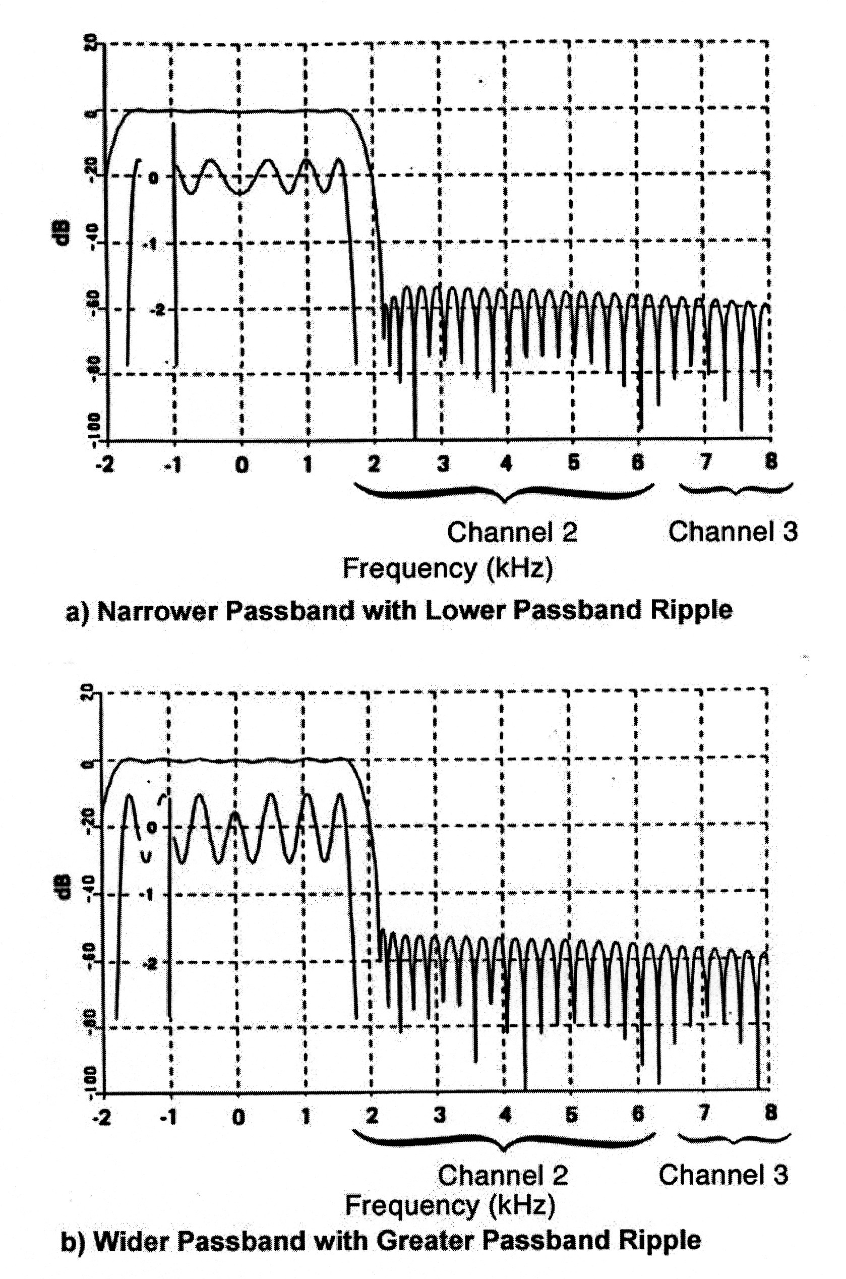
We do a first cut by evaluating to be 450 Hz, the difference between the edge of the equal-ripple passband and the point 300 Hz into the adjacent channel. Suppose that we optimistically assume that only 55 dB of suppression is needed in the stopband. Using these values, plus the fact that kHz, in [link] yields , which implies a value of . This is close to, but exceeds, a nice power of two, that is, 16. By working the filter design problem carefully it is possible to design pulse responses that do meet the requirements. Two of these are shown in [link] . One has a wide passband, at the expense of greater passband ripple, while the other trades bandwidth for ripple performance. The filter that was developed for this purpose used integral ROM to hold these pulse responses and allowed the user to control which is to be employed at a given time.
The focus of this section has been on the design of the transmultiplexer pulse response when viewed as a single tuner. In fact, most are designed this way. There are other applications however, that require that other considerations enter the design process. An example is the interference canceller discussed in A Pair of Examples from An Introduction to the FDM-TDM Digital Transmultiplexer: Appendix C . In this case, the filter pulse response is designed to bandlimit, as before, but in addition, constraints are introduced that have the effect of guaranteeing good broadband behavior as well.
Notification Switch
Would you like to follow the 'An introduction to the fdm-tdm digital transmultiplexer' conversation and receive update notifications?

|
|

|
|

|
|

|
|

|
|

|
|

|
|

|
|

|
|

|