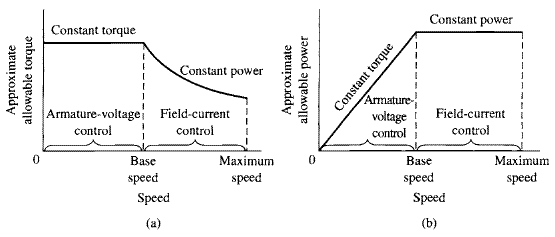
The overall output limitations are shown in Fig. 10.6a for approximate allowable torque and in Fig. 10.6b for approximate allowable power.
The constant-torque characteristic is well suited to many applications in the machinetool industry, where many loads consist largely of overcoming the friction of moving parts and hence have essentially constant torque requirements.
Figure 10.6 (a) Torque and (b) power limitations of combined armature-voltage
and field-current methods of speed control.
Figure 10.7 Block diagram for a speed-control system
for a separately excited or shunt-connected dc motor.
Figure 10.7 shows a block diagram of a feedback-control system that can be used to regulate the speed of a separately excited or shunt-connected dc motor. The inputs to the dc-motor block include the armature voltage and the field current as well as the load torque
. The resultant motor speed
is fed back to a controller block which represents both the control logic and power electronics and which controls the armature voltage and field current applied to the dc motor, based upon a reference speed signal
.
Depending upon the design of the controller, with such a scheme it is possible to control the steady-state motor speed to a high degree of accuracy independent of the variations in the load torque.
Torque control
The electromagnetic torque in the case of a separately excited or shunt motor
(10.8)
and
(10.9)
in the case of a permanent-magnet motor.
Torque can be controlled directly by controlling the armature current. Fig. 10.8 shows three possible configurations.
In Fig. 10.8a, a phase-controlled rectifier, in combination with a dc-link filter inductor, can be used to create a variable dc-link current which can be applied directly to the armature terminals of the dc motor.
In Fig. 10.8b, a constant dc-link current is produced by a diode rectifier. The armature terminal voltage is then varied by a pulse-width modulation scheme in which switch S is alternately opened and closed. When switch S is opened, the current
flows into the dc-motor armature while when switch S is closed, the armature is
Figure 10.8 Three typical configurations for armature-current control.
(a) Variable dc-link current (produced by a phase-controlled rectifier)
applied directly to the dc-motor armature terminals.
(b) Constant dc-link current with single-polarity pulse-width modulation.
(c) Constant dc-link current with a full H-bridge.
Figure 10.9 Block diagram of a dc-motor
speed-control system using direct-control of motor torque.
shorted and
decays. Thus, the duty cycle of switch S will control the average current into the armature.
Fig 10.8c shows an H-bridge configuration .Appropriate control of the four switches S 1 through S4 allows this PWM system to achieve any desired armature average current in the range
.
Note that in each of the PWM configurations of Fig. 10.8b and c, rapid changes in instantaneous current through the dc machine armature can give rise to large voltage spikes, which can damage the machine insulation as well as give rise to flashover and voltage breakdown of the commutator. In order to eliminate these effects, a practical system must include some sort of filter across the armature terminals (such as a large capacitor) to limit the voltage rise and to provide a low-impedance path for the high-frequency components of the drive current.
Figure 10.9 shows a typical configuration in which the torque control is surrounded by a speed-feedback loop. Instead of controlling the armature voltage, in this case the output of the speed controller is a torque reference signal
which in turn serves as the input to the torque controller.