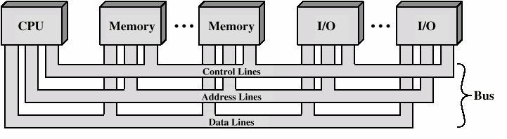
Provide a path for moving, data between system modules. These lines, collectively, are called the data bus.
The width of the data bus: The data bus may consist of from 32 to hundreds of separate lines, the number of lines being referred to as the width of the data bus. Because each line can carry only 1 bit at a time, the number of lines determines how many bits can be transferred at a lime. The width of the data bus is a key factor in determining overall system performance. For example, if the data bus is 8 bits wide and each instruction is 16 bits long, then the processor must access the memory module twice during each instruction cycle.
The address lines ( address bus):
Address lines are used to designate the source or destination of the data on the data bus. For example, if the processor wishes to read a word (8, 16. or 32 bits) of data from memory, it puts the address of the desired word on the address lines.
The width of the address bus: determines the maximum possible memory capacity of the system. Furthermore, the address lines are generally also used to address I/O ports.
The control lines (control bus):
Control bus are used to control the access to and the use of the data and address lines. Because the data and address lines are shared by all components, there must be a means of controlling their use. Control signals transmit both command and liming information between system modules. Timing signals indicate the validity of data and address information.
Command signals specify operations to be performed. Typical control lines include the following:
Memory write: Causes data on the bus to be written into the addressed location.
Memory read: Causes data from the addressed location to be placed on the bus.
I/O write: Causes data on the bus to be output to the addressed I/O port.
I/O read: Causes data from the addressed I/O port to be placed on the bus.
Transfer ACK: Indicates that data have been accepted from or placed on the bus.
Bus request: Indicates that a module needs to gain control of the bus.
Bus grant: Indicates that a requesting module has been granted control of the bus.
Interrupt request: Indicates that an interrupt is pending.
Interrupt ACK: Acknowledges that the pending interrupt has been recognized.
Clock: Used to synchronize operations.
Reset: Initializes all modules.
Figure 12 Bus Interconnection Scheme
Multiple-bus hierarchies
If a great number of devices are connected to the bus, performance will suffer. There are two main causes:
In general, the more devices attached to the bus, the greater the bus length and hence the greater the propagation delay. This delay determines the time it takes for devices to coordinate the use of the bus. When control of the bus passes from one device to another frequently, these propagation delays can noticeably affect performance.
The bus may become a bottleneck as the aggregate data transfer demand approaches the capacity of the bus. This problem can be countered to some extent by increasing the data rate that the bus can carry and by using wider buses (e.g., increasing the data bus from 32 to 64 bit). However, because the data rates generated by attached devices (e.g.. graphics and video controllers, network interfaces) are growing rapidly, this is a race that a single bus is ultimately destined to lose.
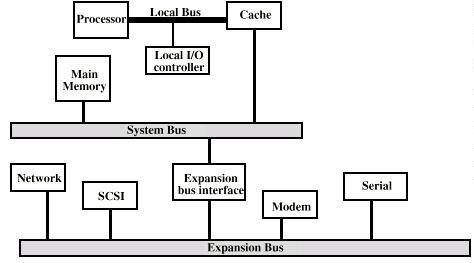
Accordingly, most computer systems use multiple buses, generally laid out in a hierarchy. A typical traditional structure is shown in Figure 13. There is a local bus that connects the processor to a cache memory and that may support one or more local devices. The cache memory controller connects the cache not only to this local bus, but to a system bus to which are attached all of the main memory modules.
It is possible to connected I/O controllers directly onto the system bus. A more efficient solution is to make use of one or more expansion buses for this purpose. An expansion bus interface buffers data transfers between the system bus and the I/O controllers on the expansion bus. This arrangement allows the system to support a wide variety of I/O devices and at the same time insulate memory-to-processor traffic from I/O traffic.