The Simulink block will be created from the AIC23 driver used in the “Custom Device Driver/Legacy Code Integration” Simulink demo.
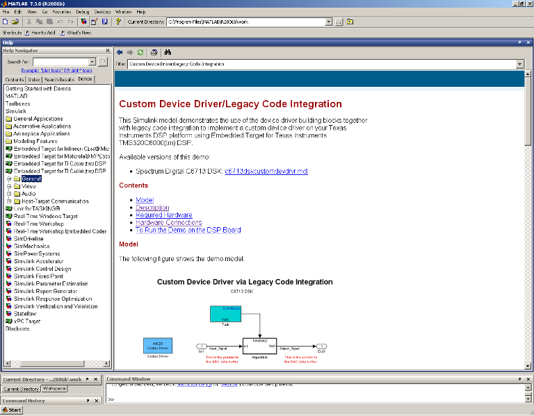
Open the demo
The Simulink demo for Device Driver/Legacy Code Integration
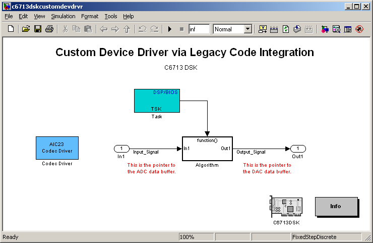
Open the model
Real-time model using a custom device driver
Double-click the "AIC23 Codec Driver" box.
Rename it (TLV320AIC24EVM).
Delete the EDMA related boxes
The EDMA and interrupts configurations are handled as in the original CCS driver. .
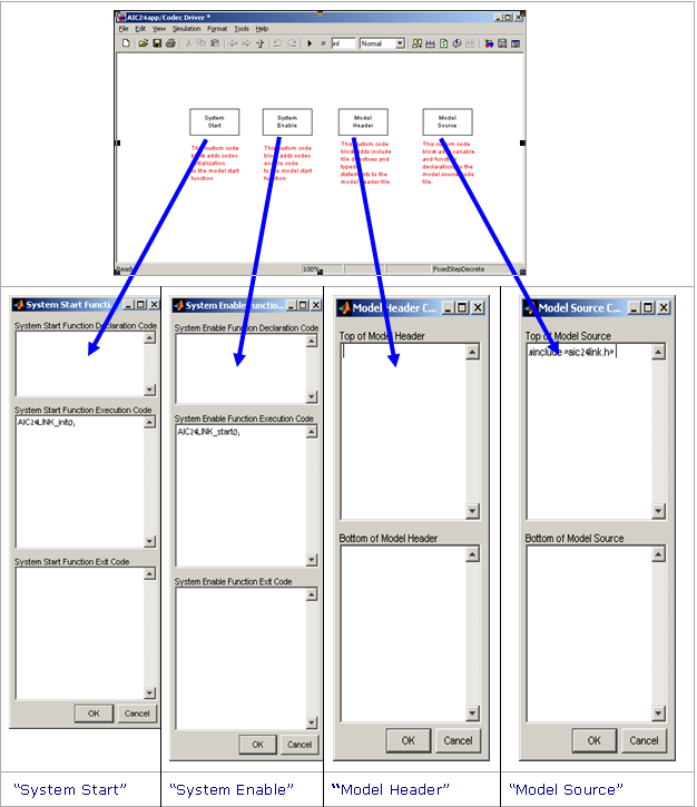
Double-click the "System Start" box. Delete the code and replace it by the initialization function AIC24LINK_init () in the execution box.
Double-click the "System Enable". Delete the code and add the AIC24LINK_Start(), to the execution box.
Delete the code in the "Model Header" box.
Double-click the "Model Source" box. Delete the code. Add to the "Top of Model Source" box the line #include "aic24link.h". This will allow calling the functions in the aic24link.c file. Figure 17 summarizes the driver blocks configuration
TLV320AIC24EVM driver blocks
The next steps will guide you through the “Algorithm” block configuration
Add 6 terminators (inputs and outputs) both inside and outside the "Algorithm" box and of course wiring them appropriately. Double click on each terminator and set its dimension to 64
The terminator dimension should match the value of the DATANUM constant in the aic24link.c file (except for the internal terminators). Set the data type to int16.The 8 input and output ports should be linked to the buffers (i.e. the pointers) in the aic24link.c file.
Right-click the wires connecting the terminators to the algorithm and select "Signal Properties". A new window will be opened window, Select "RealTime Workshop" tab and "ImportedExternPointer". Enter the signal name. It should have the same name of the correspondent pointers in the driver (As defined in the aic24link.c file).
Double-click the "Algorithm" box again and then open the "System Outputs" block. Delete the code and add a call to AIC24LINK_wait. This way the loop of the task stops each time and waits for the data.
The “Algorithm” block
The model is now ready to generate real-time code for processing of 4 audio channels. AN example is shown in the next chapter.
The audio conference bridge application
This chapter illustrates the use of the Simulink driver introduced in the previous chapter, to implement a conference bridge.
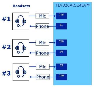
Figure 15 shows the configuration used for this application. Three headsets
The TLV320AIC24 contains three analog interfaces for headsets. The use of an additional channel requires minor hardware changes in the board. are used, enabling a 3-port conference. The DSP monitors the 3 input signals, and routes the “loudest” input signal to the three outputs. The algorithm is described in the next section.
System Configuration
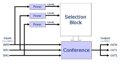
The algorithm
The Algorithm (Block Diagram)
The algorithm processes 64 samples (each channel). It calculates the absolute power of each channel (sum of absolute values). Three counters are used, each one corresponding to a distinct channel.
Receive real-time job alerts and never miss the right job again
Source:
OpenStax, From matlab and simulink to real-time with ti dsp's. OpenStax CNX. Jun 08, 2009 Download for free at http://cnx.org/content/col10713/1.1
Google Play and the Google Play logo are trademarks of Google Inc.
Notification Switch
Would you like to follow the 'From matlab and simulink to real-time with ti dsp's' conversation and receive update notifications?