<< Chapter < Page Chapter >> Page >
By the end of this section, you will be able to:
  • Describe the combined effect of interference and diffraction with two slits, each with finite width
  • Determine the relative intensities of interference fringes within a diffraction pattern
  • Identify missing orders, if any

When we studied interference in Young’s double-slit experiment, we ignored the diffraction effect in each slit. We assumed that the slits were so narrow that on the screen you saw only the interference of light from just two point sources. If the slit is smaller than the wavelength, then [link] (a) shows that there is just a spreading of light and no peaks or troughs on the screen. Therefore, it was reasonable to leave out the diffraction effect in that chapter. However, if you make the slit wider, [link] (b) and (c) show that you cannot ignore diffraction. In this section, we study the complications to the double-slit experiment that arise when you also need to take into account the diffraction effect of each slit.

To calculate the diffraction pattern for two (or any number of) slits, we need to generalize the method we just used for a single slit. That is, across each slit, we place a uniform distribution of point sources that radiate Huygens wavelets, and then we sum the wavelets from all the slits. This gives the intensity at any point on the screen. Although the details of that calculation can be complicated, the final result is quite simple:

Two-slit diffraction pattern

The diffraction pattern of two slits of width D that are separated by a distance d is the interference pattern of two point sources separated by d multiplied by the diffraction pattern of a slit of width D .

In other words, the locations of the interference fringes are given by the equation d sin θ = m λ , the same as when we considered the slits to be point sources, but the intensities of the fringes are now reduced by diffraction effects, according to [link] . [Note that in the chapter on interference, we wrote d sin θ = m λ and used the integer m to refer to interference fringes. [link] also uses m , but this time to refer to diffraction minima. If both equations are used simultaneously, it is good practice to use a different variable (such as n ) for one of these integers in order to keep them distinct.]

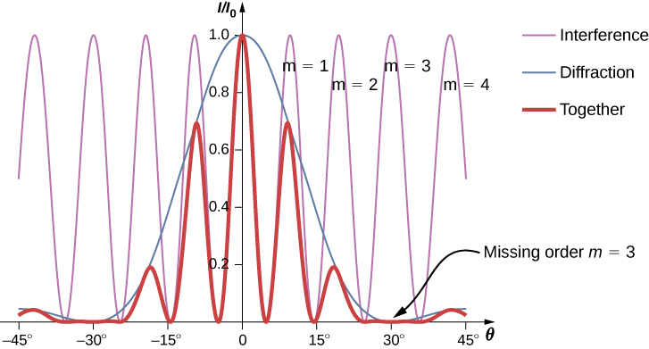
Interference and diffraction effects operate simultaneously and generally produce minima at different angles. This gives rise to a complicated pattern on the screen, in which some of the maxima of interference from the two slits are missing if the maximum of the interference is in the same direction as the minimum of the diffraction. We refer to such a missing peak as a missing order    . One example of a diffraction pattern on the screen is shown in [link] . The solid line with multiple peaks of various heights is the intensity observed on the screen. It is a product of the interference pattern of waves from separate slits and the diffraction of waves from within one slit.

Figure shows a graph of I by I0 versus theta. Three curves are shown on the graph. Interference curve has a smaller wavelength. Diffraction curve has a larger wavelength and a y value of 1 at x equal to 0. Resultant curve has the same wavelength as the interference and its amplitude is modified according to the diffraction curve. Each wave crest of the interference wave is labeled m equal to 1, m equal to 2 and so on. The diffraction wave has a zero at m equal to 3, and theta equal to 30 degrees. Hence, the resultant wave, too, has a zero. This is labeled missing order m equal to 3.
Diffraction from a double slit. The purple line with peaks of the same height are from the interference of the waves from two slits; the blue line with one big hump in the middle is the diffraction of waves from within one slit; and the thick red line is the product of the two, which is the pattern observed on the screen. The plot shows the expected result for a slit width D = 2 λ and slit separation d = 6 λ . The maximum of m = ± 3 order for the interference is missing because the minimum of the diffraction occurs in the same direction.

Questions & Answers

what is force
Afework Reply
The different examples for collision
Afework
What is polarization and there are type
Muhammed Reply
Polarization is the process of transforming unpolarized light into polarized light. types of polarization 1. linear polarization. 2. circular polarization. 3. elliptical polarization.
Eze
Describe what you would see when looking at a body whose temperature is increased from 1000 K to 1,000,000 K
Aishwarya Reply
how is tan ninety minus an angle equals to cot an angle?
Niicommey Reply
please I don't understand all about this things going on here
Jeremiah Reply
What is torque?
Matthew Reply
In physics and mechanics, torque is the rotational equivalent of linear force. It is also referred to as the moment, moment of force, rotational force or turning effect, depending on the field of study.
Teka
Torque refers to the rotational force. i.e Torque = Force × radius.
Arun
Torque is the rotational equivalent of force . Specifically, it is a force exerted at a distance from an object's axis of rotation. In the same way that a force applied to an object will cause it to move linearly, a torque applied to an object will cause it to rotate around a pivot point.
Teka
Torque is the rotational equivalence of force . So, a net torque will cause an object to rotate with an angular acceleration. Because all rotational motions have an axis of rotation, a torque must be defined about a rotational axis. A torque is a force applied to a point on an object about the axis
Teka
When a missle is shot from one spaceship towards another, it leaves the first at 0.950c and approaches the other at 0.750c. what is the relative velocity of the two shipd
Marifel Reply
how to convert:m^3/s^2 all divided by kg to cm^3/s^2
Thibaza Reply
Is there any proof of existence of luminiferious aether ?
Zero Reply
mass conversion of 58.73kg =mg
Proactive Reply
is Space time fabric real
Godawari Reply
What's the relationship between the work function and the cut off frequency in the diagram above?
frankline Reply
due to the upthrust weight of the object varise with force in which the body fall into the water pendincular with the reflection of light with it
Gift
n=I/r
Gift
can someone explain what is going on here
falanga
so some pretty easy physics questions bring em
falanga
what is meant by fluctuated
Olasukanmi Reply
If n=cv then how v=cn? and if n=c/v then how v=cn?
Natanim
convert feet to metre
Mbah Reply
what is electrolysis
Mbah
Electrolysis is the chemical decomposition of electrolyte either in molten state or solution to conduct electricity
Ayomide
class ninekasindhtextbookurdusave
Ayesha Reply
can someone help explain why v2/c2 is =1/2 Using The Lorentz Transformation For Time Spacecraft S′ is on its way to Alpha Centauri when Spacecraft S passes it at relative speed c /2. The captain of S′ sends a radio signal that lasts 1.2 s according to that ship’s clock. Use the Lorentz transformati
Jennifer
Practice Key Terms 2

Get Jobilize Job Search Mobile App in your pocket Now!

Get it on Google Play Download on the App Store Now


Source:  OpenStax, University physics volume 3. OpenStax CNX. Nov 04, 2016 Download for free at http://cnx.org/content/col12067/1.4
Google Play and the Google Play logo are trademarks of Google Inc.

Notification Switch

Would you like to follow the 'University physics volume 3' conversation and receive update notifications?

Ask