<< Chapter < Page Chapter >> Page >
By the end of this section, you will be able to:
  • Calculate the intensity relative to the central maximum of the single-slit diffraction peaks
  • Calculate the intensity relative to the central maximum of an arbitrary point on the screen

To calculate the intensity of the diffraction pattern, we follow the phasor method used for calculations with ac circuits in Alternating-Current Circuits . If we consider that there are N Huygens sources across the slit shown in [link] , with each source separated by a distance D/N from its adjacent neighbors, the path difference between waves from adjacent sources reaching the arbitrary point P on the screen is ( D / N ) sin θ . This distance is equivalent to a phase difference of ( 2 π D / λ N ) sin θ . The phasor diagram for the waves arriving at the point whose angular position is θ is shown in [link] . The amplitude of the phasor for each Huygens wavelet is Δ E 0 , the amplitude of the resultant phasor is E , and the phase difference between the wavelets from the first and the last sources is

ϕ = ( 2 π λ ) D sin θ .

With N , the phasor diagram approaches a circular arc of length N Δ E 0 and radius r . Since the length of the arc is N Δ E 0 for any ϕ , the radius r of the arc must decrease as ϕ increases (or equivalently, as the phasors form tighter spirals).

Figure a shows an arc with phasors labeled delta E subscript 0. This subtends an angle at the center of the circle, through two lines labeled r. This angle is bisected and each half is labeled phi by 2. The endpoints of the arc are connected by an arrow labeled E. The tangent at one endpoint of the arc is horizontal. The tangent at the other endpoint of the arc makes an angle phi with the horizontal. Figure b shows the arc and the angle phi subtended by it. A dotted line extends from one endpoint of the arc to the opposite line r. It is perpendicular to r. It makes an angle phi with the arc and an angle 90 minus phi with the adjacent line r.
(a) Phasor diagram corresponding to the angular position θ in the single-slit diffraction pattern. The phase difference between the wavelets from the first and last sources is ϕ = ( 2 π / λ ) D sin θ . (b) The geometry of the phasor diagram.

The phasor diagram for ϕ = 0 (the center of the diffraction pattern) is shown in [link] (a) using N = 30 . In this case, the phasors are laid end to end in a straight line of length N Δ E 0 , the radius r goes to infinity, and the resultant has its maximum value E = N Δ E 0 . The intensity of the light can be obtained using the relation I = 1 2 c ε 0 E 2 from Electromagnetic Waves . The intensity of the maximum is then

I 0 = 1 2 c ε 0 ( N Δ E 0 ) 2 = 1 2 μ 0 c ( N Δ E 0 ) 2 ,

where ε 0 = 1 / μ 0 c 2 . The phasor diagrams for the first two zeros of the diffraction pattern are shown in parts (b) and (d) of the figure. In both cases, the phasors add to zero, after rotating through ϕ = 2 π rad for m = 1 and 4 π rad for m = 2 .

Figure a shows 30 phasors in a line of length N delta E subscript 0. The length of a phasor is delta E subscript 0. Figure b shows a circle with phasors pointing in the anticlockwise direction. This is labeled m equal to 1, E equal to 0. Figure c shows phasors along a circle. They start from the bottom and go one and a half times around the circle in the anticlockwise direction. An arrow from the starting point to the ending point is labeled E1. It forms a diameter of the circle. Figure c is labeled 3 by 2 pi E1 equal to N delta E0. Figure d shows phasors along a circle. They start from the bottom and go twice around the circle in the anticlockwise direction. The figure is labeled m equal to 2, E equal to 0. Figure e shows phasors along a circle. They start from the bottom and go two and a half times around the circle in the anticlockwise direction. An arrow from the starting point to the ending point is labeled E2. It forms a diameter of the circle. Figure c is labeled 5 by 2 pi E2 equal to N delta E0.
Phasor diagrams (with 30 phasors) for various points on the single-slit diffraction pattern. Multiple rotations around a given circle have been separated slightly so that the phasors can be seen. (a) Central maximum, (b) first minimum, (c) first maximum beyond central maximum, (d) second minimum, and (e) second maximum beyond central maximum.

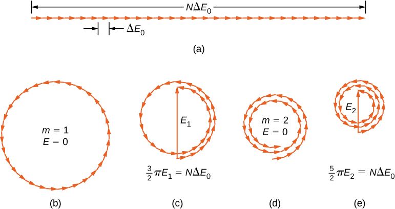
The next two maxima beyond the central maxima are represented by the phasor diagrams of parts (c) and (e). In part (c), the phasors have rotated through ϕ = 3 π rad and have formed a resultant phasor of magnitude E 1 . The length of the arc formed by the phasors is N Δ E 0 . Since this corresponds to 1.5 rotations around a circle of diameter E 1 , we have

3 2 π E 1 = N Δ E 0 ,

so

E 1 = 2 N Δ E 0 3 π

and

I 1 = 1 2 μ 0 c E 1 2 = 4 ( N Δ E 0 ) 2 ( 9 π 2 ) ( 2 μ 0 c ) = 0.045 I 0 ,

where

I 0 = ( N Δ E 0 ) 2 2 μ 0 c .

In part (e), the phasors have rotated through ϕ = 5 π rad, corresponding to 2.5 rotations around a circle of diameter E 2 and arc length N Δ E 0 . This results in I 2 = 0.016 I 0 . The proof is left as an exercise for the student ( [link] ).

Questions & Answers

what is biology
Hajah Reply
the study of living organisms and their interactions with one another and their environments
AI-Robot
what is biology
Victoria Reply
HOW CAN MAN ORGAN FUNCTION
Alfred Reply
the diagram of the digestive system
Assiatu Reply
allimentary cannel
Ogenrwot
How does twins formed
William Reply
They formed in two ways first when one sperm and one egg are splited by mitosis or two sperm and two eggs join together
Oluwatobi
what is genetics
Josephine Reply
Genetics is the study of heredity
Misack
how does twins formed?
Misack
What is manual
Hassan Reply
discuss biological phenomenon and provide pieces of evidence to show that it was responsible for the formation of eukaryotic organelles
Joseph Reply
what is biology
Yousuf Reply
the study of living organisms and their interactions with one another and their environment.
Wine
discuss the biological phenomenon and provide pieces of evidence to show that it was responsible for the formation of eukaryotic organelles in an essay form
Joseph Reply
what is the blood cells
Shaker Reply
list any five characteristics of the blood cells
Shaker
lack electricity and its more savely than electronic microscope because its naturally by using of light
Abdullahi Reply
advantage of electronic microscope is easily and clearly while disadvantage is dangerous because its electronic. advantage of light microscope is savely and naturally by sun while disadvantage is not easily,means its not sharp and not clear
Abdullahi
cell theory state that every organisms composed of one or more cell,cell is the basic unit of life
Abdullahi
is like gone fail us
DENG
cells is the basic structure and functions of all living things
Ramadan
What is classification
ISCONT Reply
is organisms that are similar into groups called tara
Yamosa
in what situation (s) would be the use of a scanning electron microscope be ideal and why?
Kenna Reply
A scanning electron microscope (SEM) is ideal for situations requiring high-resolution imaging of surfaces. It is commonly used in materials science, biology, and geology to examine the topography and composition of samples at a nanoscale level. SEM is particularly useful for studying fine details,
Hilary
cell is the building block of life.
Condoleezza Reply
Got questions? Join the online conversation and get instant answers!
Jobilize.com Reply
Practice Key Terms 1

Get Jobilize Job Search Mobile App in your pocket Now!

Get it on Google Play Download on the App Store Now


Source:  OpenStax, University physics volume 3. OpenStax CNX. Nov 04, 2016 Download for free at http://cnx.org/content/col12067/1.4
Google Play and the Google Play logo are trademarks of Google Inc.

Notification Switch

Would you like to follow the 'University physics volume 3' conversation and receive update notifications?

Ask