<< Chapter < Page Chapter >> Page >
By the end of this section, you will be able to:
  • Determine the angles for bright and dark fringes for double slit interference
  • Calculate the positions of bright fringes on a screen

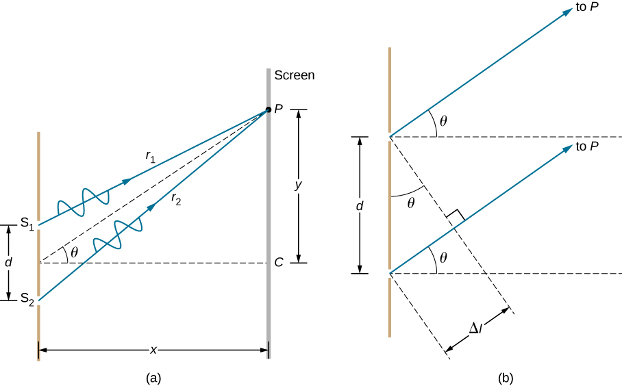
[link] (a) shows how to determine the path length difference Δ l for waves traveling from two slits to a common point on a screen. If the screen is a large distance away compared with the distance between the slits, then the angle θ between the path and a line from the slits to the screen [part (b)] is nearly the same for each path. In other words, r 1 and r 2 are essentially parallel. The lengths of r 1 and r 2 differ by Δ l , as indicated by the two dashed lines in the figure. Simple trigonometry shows

Δ l = d sin θ

where d is the distance between the slits. Combining this result with [link] , we obtain constructive interference for a double slit when the path length difference is an integral multiple of the wavelength, or

d sin θ = m λ , for m = 0 , ± 1 , ± 2 , ± 3 ,… (constructive interference) .

Similarly, to obtain destructive interference for a double slit, the path length difference must be a half-integral multiple of the wavelength, or

d sin θ = ( m + 1 2 ) λ , for m = 0 , ± 1 , ± 2 , ± 3 ,… (destructive interference)

where λ is the wavelength of the light, d is the distance between slits, and θ is the angle from the original direction of the beam as discussed above. We call m the order    of the interference. For example, m = 4 is fourth-order interference.

Left picture is a schematic drawing that shows waves r1 and r2 passing through the two slits S1 and S2. The waves meet in a common point P on a screen. Distance between points S1 and S2 is d; distance between the screen with the two slits and the screen with point P is x. Point P is higher than the mid-point between S1 and S2 by the distance y. Imaginary line drawn from the point P to the mid-point between slits form an angle Theta with the x axis. Right picture is a schematic drawing that two slits separated by the distance d. Waves pass through the slits and travel to the screen P. Angle theta is formed by the travelling wave and x axis.
(a) To reach P , the light waves from S 1 and S 2 must travel different distances. (b) The path difference between the two rays is Δ l .

The equations for double-slit interference imply that a series of bright and dark lines are formed. For vertical slits, the light spreads out horizontally on either side of the incident beam into a pattern called interference fringes    ( [link] ). The closer the slits are, the more the bright fringes spread apart. We can see this by examining the equation

d sin θ = m λ , for m = 0 , ± 1 , ± 2 , ± 3 . For fixed λ and m , the smaller d is, the larger θ must be, since sin θ = m λ / d . This is consistent with our contention that wave effects are most noticeable when the object the wave encounters (here, slits a distance d apart) is small. Small d gives large θ , hence, a large effect.

Referring back to part (a) of the figure, θ is typically small enough that sin θ tan θ y m / D , where y m is the distance from the central maximum to the m th bright fringe and D is the distance between the slit and the screen. [link] may then be written as

d y m D = m λ

or

y m = m λ D d .
Left picture shows a double slit located a distance D from a screen, with the distance between the slits given as d. Right picture is a photograph of the fringe pattern that shows the bright lines at the positions where the waves interfere constructively.
The interference pattern for a double slit has an intensity that falls off with angle. The image shows multiple bright and dark lines, or fringes, formed by light passing through a double slit.

Finding a wavelength from an interference pattern

Suppose you pass light from a He-Ne laser through two slits separated by 0.0100 mm and find that the third bright line on a screen is formed at an angle of 10.95 ° relative to the incident beam. What is the wavelength of the light?

Strategy

The phenomenon is two-slit interference as illustrated in [link] and the third bright line is due to third-order constructive interference, which means that m = 3 . We are given d = 0.0100 mm and θ = 10.95 ° . The wavelength can thus be found using the equation d sin θ = m λ for constructive interference.

Solution

Solving d sin θ = m λ for the wavelength λ gives

λ = d sin θ m .

Substituting known values yields

λ = ( 0.0100 mm ) ( sin 10.95 ° ) 3 = 6.33 × 10 −4 mm = 633 nm .

Significance

To three digits, this is the wavelength of light emitted by the common He-Ne laser. Not by coincidence, this red color is similar to that emitted by neon lights. More important, however, is the fact that interference patterns can be used to measure wavelength. Young did this for visible wavelengths. This analytical techinque is still widely used to measure electromagnetic spectra. For a given order, the angle for constructive interference increases with λ , so that spectra (measurements of intensity versus wavelength) can be obtained.

Got questions? Get instant answers now!
Practice Key Terms 2

Get Jobilize Job Search Mobile App in your pocket Now!

Get it on Google Play Download on the App Store Now


Source:  OpenStax, University physics volume 3. OpenStax CNX. Nov 04, 2016 Download for free at http://cnx.org/content/col12067/1.4
Google Play and the Google Play logo are trademarks of Google Inc.

Notification Switch

Would you like to follow the 'University physics volume 3' conversation and receive update notifications?

Ask