<< Chapter < Page Chapter >> Page >
Figure shows the cross section of a bi-convex lens. The radii of curvature of the right and left surfaces are R1 and R2 respectively. The thickness of the lens is h. Light ray 1 enters the lens, deviates and passes through the focal point. Light ray 2 passes through the center of the lens without deviating.
In the thin-lens approximation, the thickness d of the lens is much, much less than the radii R 1 and R 2 of curvature of the surfaces of the lens. Light rays are considered to bend at the center of the lens, such as light ray 1. Light ray 2 passes through the center of the lens and is undeviated in the thin-lens approximation.

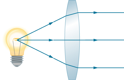
As noted in the initial discussion of Snell’s law, the paths of light rays are exactly reversible. This means that the direction of the arrows could be reversed for all of the rays in [link] . For example, if a point-light source is placed at the focal point of a convex lens, as shown in [link] , parallel light rays emerge from the other side.

Figure shows rays from a light bulb entering a bi-convex lens and emerging on the other side as parallel rays.
A small light source, like a light bulb filament, placed at the focal point of a convex lens results in parallel rays of light emerging from the other side. The paths are exactly the reverse of those shown in [link] in converging and diverging lenses. This technique is used in lighthouses and sometimes in traffic lights to produce a directional beam of light from a source that emits light in all directions.

Ray tracing and thin lenses

Ray tracing is the technique of determining or following (tracing) the paths taken by light rays.

Ray tracing for thin lenses is very similar to the technique we used with spherical mirrors. As for mirrors, ray tracing    can accurately describe the operation of a lens. The rules for ray tracing for thin lenses are similar to those of spherical mirrors:

  1. A ray entering a converging lens parallel to the optical axis passes through the focal point on the other side of the lens (ray 1 in part (a) of [link] ). A ray entering a diverging lens parallel to the optical axis exits along the line that passes through the focal point on the same side of the lens (ray 1 in part (b) of the figure).
  2. A ray passing through the center of either a converging or a diverging lens is not deviated (ray 2 in parts (a) and (b)).
  3. For a converging lens, a ray that passes through the focal point exits the lens parallel to the optical axis (ray 3 in part (a)). For a diverging lens, a ray that approaches along the line that passes through the focal point on the opposite side exits the lens parallel to the axis (ray 3 in part (b)).
Figure a shows a bi-convex lens with focal points on both sides. An object is placed on its optical axis. Three rays originate from the top of this object and enter the lens. Ray 1 is parallel to the optical axis. Ray 2 strikes the center of the lens. Ray 3 crosses the focal point before entering the lens. The rays converge on the other side to form an image. Ray 1 crosses the focal point and ray 3 is now parallel to the axis. Figure b shows a bi-concave lens with focal points on both sides. An object is placed on its optical axis. Three rays originate from the top of this object and enter the lens. Ray 1 is parallel to the axis, ray 2 strikes the center of the lens and ray 3, if extended in a straight line would cross the focal point on the other side of the lens. All three rays diverge on the other side of the lens. Ray 3 is now parallel to the axis and the back extension of ray 1 crosses the focal point in front of the lens. The back extensions of all three rays converge to form a virtual image, that is much smaller than the object, in front of the lens.
Thin lenses have the same focal lengths on either side. (a) Parallel light rays entering a converging lens from the right cross at its focal point on the left. (b) Parallel light rays entering a diverging lens from the right seem to come from the focal point on the right.

Thin lenses work quite well for monochromatic light (i.e., light of a single wavelength). However, for light that contains several wavelengths (e.g., white light), the lenses work less well. The problem is that, as we learned in the previous chapter, the index of refraction of a material depends on the wavelength of light. This phenomenon is responsible for many colorful effects, such as rainbows. Unfortunately, this phenomenon also leads to aberrations in images formed by lenses. In particular, because the focal distance of the lens depends on the index of refraction, it also depends on the wavelength of the incident light. This means that light of different wavelengths will focus at different points, resulting is so-called “chromatic aberrations.” In particular, the edges of an image of a white object will become colored and blurred. Special lenses called doublets are capable of correcting chromatic aberrations . A doublet is formed by gluing together a converging lens and a diverging lens. The combined doublet lens produces significantly reduced chromatic aberrations.

Practice Key Terms 5

Get Jobilize Job Search Mobile App in your pocket Now!

Get it on Google Play Download on the App Store Now


Source:  OpenStax, University physics volume 3. OpenStax CNX. Nov 04, 2016 Download for free at http://cnx.org/content/col12067/1.4
Google Play and the Google Play logo are trademarks of Google Inc.

Notification Switch

Would you like to follow the 'University physics volume 3' conversation and receive update notifications?

Ask