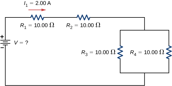
Two resistors connected in series
are connected to two resistors that are connected in parallel
. The series-parallel combination is connected to a battery. Each resistor has a resistance of 10.00 Ohms. The wires connecting the resistors and battery have negligible resistance. A current of 2.00 Amps runs through resistor
What is the voltage supplied by the voltage source?
Strategy
Use the steps in the preceding problem-solving strategy to find the solution for this example.
Solution
Draw a clear circuit diagram (
[link] ).
To find the unknown voltage, we must first find the equivalent resistance of the circuit.
The unknown is the voltage of the battery. In order to find the voltage supplied by the battery, the equivalent resistance must be found.
In this circuit, we already know that the resistors
and
are in series and the resistors
and
are in parallel. The equivalent resistance of the parallel configuration of the resistors
and
is in series with the series configuration of resistors
and
.
The voltage supplied by the battery can be found by multiplying the current from the battery and the equivalent resistance of the circuit. The current from the battery is equal to the current through
and is equal to 2.00 A. We need to find the equivalent resistance by reducing the circuit. To reduce the circuit, first consider the two resistors in parallel. The equivalent resistance is
This parallel combination is in series with the other two resistors, so the equivalent resistance of the circuit is
The voltage supplied by the battery is therefore
One way to check the consistency of your results is to calculate the power supplied by the battery and the power dissipated by the resistors. The power supplied by the battery is
Since they are in series, the current through
equals the current through
Since
, the current through each will be 1.00 Amps. The power dissipated by the resistors is equal to the sum of the power dissipated by each resistor:
Since the power dissipated by the resistors equals the power supplied by the battery, our solution seems consistent.
Significance
If a problem has a combination of series and parallel, as in this example, it can be reduced in steps by using the preceding problem-solving strategy and by considering individual groups of series or parallel connections. When finding
for a parallel connection, the reciprocal must be taken with care. In addition, units and numerical results must be reasonable. Equivalent series resistance should be greater, whereas equivalent parallel resistance should be smaller, for example. Power should be greater for the same devices in parallel compared with series, and so on.
Summary
The equivalent resistance of an electrical circuit with resistors wired in a series is the sum of the individual resistances:
.
Each resistor in a series circuit has the same amount of current flowing through it.
The potential drop, or power dissipation, across each individual resistor in a series is different, and their combined total is the power source input.
The equivalent resistance of an electrical circuit with resistors wired in parallel is less than the lowest resistance of any of the components and can be determined using the formula
Each resistor in a parallel circuit has the same full voltage of the source applied to it.
The current flowing through each resistor in a parallel circuit is different, depending on the resistance.
If a more complex connection of resistors is a combination of series and parallel, it can be reduced to a single equivalent resistance by identifying its various parts as series or parallel, reducing each to its equivalent, and continuing until a single resistance is eventually reached.