| << Chapter < Page | Chapter >> Page > |
Another example dealing with multiple voltage sources is that of combinations of solar cells —wired in both series and parallel combinations to yield a desired voltage and current. Photovoltaic generation, which is the conversion of sunlight directly into electricity, is based upon the photoelectric effect. The photoelectric effect is beyond the scope of this chapter and is covered in Photons and Matter Waves , but in general, photons hitting the surface of a solar cell create an electric current in the cell.
Most solar cells are made from pure silicon. Most single cells have a voltage output of about 0.5 V, while the current output is a function of the amount of sunlight falling on the cell (the incident solar radiation known as the insolation). Under bright noon sunlight, a current per unit area of about of cell surface area is produced by typical single-crystal cells.
Individual solar cells are connected electrically in modules to meet electrical energy needs. They can be wired together in series or in parallel—connected like the batteries discussed earlier. A solar-cell array or module usually consists of between 36 and 72 cells, with a power output of 50 W to 140 W.
Solar cells, like batteries, provide a direct current (dc) voltage. Current from a dc voltage source is unidirectional. Most household appliances need an alternating current (ac) voltage.
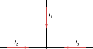
Can all of the currents going into the junction shown below be positive? Explain.
Consider the circuit shown below. Does the analysis of the circuit require Kirchhoff’s method, or can it be redrawn to simplify the circuit? If it is a circuit of series and parallel connections, what is the equivalent resistance?

It can be redrawn.
Do batteries in a circuit always supply power to a circuit, or can they absorb power in a circuit? Give an example.
What are the advantages and disadvantages of connecting batteries in series? In parallel?
In series the voltages add, but so do the internal resistances, because the internal resistances are in series. In parallel, the terminal voltage is the same, but the equivalent internal resistance is smaller than the smallest individual internal resistance and a higher current can be provided.
Semi-tractor trucks use four large 12-V batteries. The starter system requires 24 V, while normal operation of the truck’s other electrical components utilizes 12 V. How could the four batteries be connected to produce 24 V? To produce 12 V? Why is 24 V better than 12 V for starting the truck’s engine (a very heavy load)?
Consider the circuit shown below. (a) Find the voltage across each resistor. (b)What is the power supplied to the circuit and the power dissipated or consumed by the circuit?
Consider the circuits shown below. (a) What is the current through each resistor in part (a)? (b) What is the current through each resistor in part (b)? (c) What is the power dissipated or consumed by each circuit? (d) What is the power supplied to each circuit?
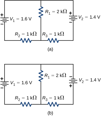
a.
;
b.
; c.
;
d.
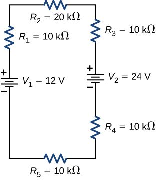
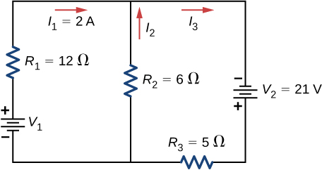
Consider the circuit shown below. Find
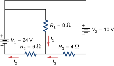
Consider the circuit shown below. Find
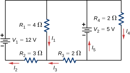
Consider the circuit shown below. (a) Find (b) Find the power supplied by the voltage sources. (c) Find the power dissipated by the resistors.
a.
; b.
;
c.
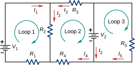
Consider the circuit shown below. Write the three loop equations for the loops shown.
Consider the circuit shown below. Write equations for the three currents in terms of R and V .
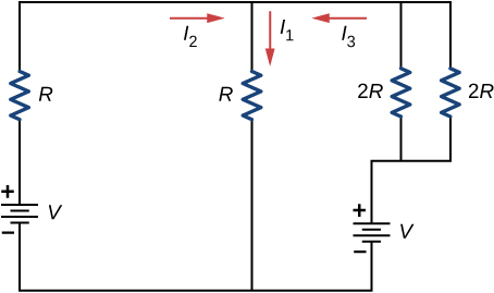
Consider the circuit shown in the preceding problem. Write equations for the power supplied by the voltage sources and the power dissipated by the resistors in terms of R and V .
A child’s electronic toy is supplied by three 1.58-V alkaline cells having internal resistances of in series with a 1.53-V carbon-zinc dry cell having a internal resistance. The load resistance is . (a) Draw a circuit diagram of the toy and its batteries. (b) What current flows? (c) How much power is supplied to the load? (d) What is the internal resistance of the dry cell if it goes bad, resulting in only 0.500 W being supplied to the load?
a.
 ;
;
b. 0.617 A; c. 3.81 W; d.
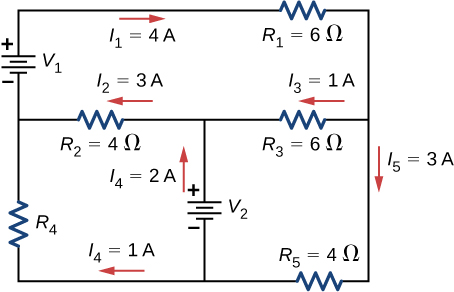
Apply the junction rule to Junction b shown below. Is any new information gained by applying the junction rule at e ?
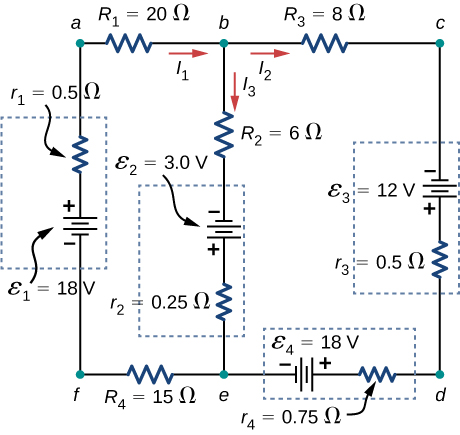
Apply the loop rule to Loop afedcba in the preceding problem.
Notification Switch
Would you like to follow the 'University physics volume 2' conversation and receive update notifications?

|
|

|
|

|
|

|
|

|
|
|
|

|
|
|
|

|
|

|