

| << Chapter < Page | Chapter >> Page > |
Check Your Understanding Circuit breakers in a home are rated in amperes, normally in a range from 10 amps to 30 amps, and are used to protect the residents from harm and their appliances from damage due to large currents. A single 15-amp circuit breaker may be used to protect several outlets in the living room, whereas a single 20-amp circuit breaker may be used to protect the refrigerator in the kitchen. What can you deduce from this about current used by the various appliances?
The total current needed by all the appliances in the living room (a few lamps, a television, and your laptop) draw less current and require less power than the refrigerator.
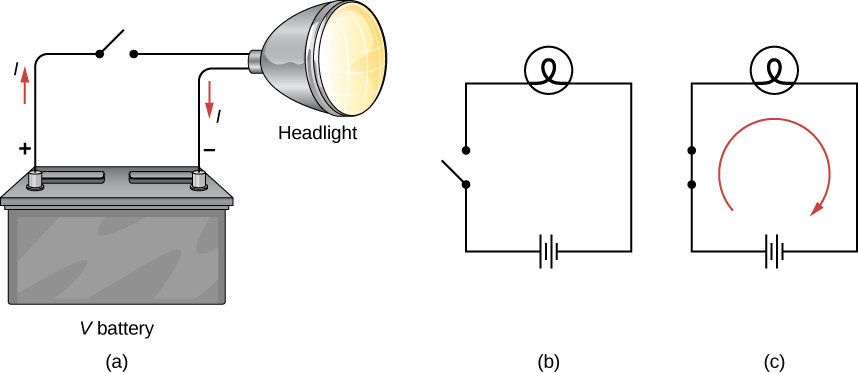
In the previous paragraphs, we defined the current as the charge that flows through a cross-sectional area per unit time. In order for charge to flow through an appliance, such as the headlight shown in [link] , there must be a complete path (or circuit ) from the positive terminal to the negative terminal. Consider a simple circuit of a car battery, a switch, a headlight lamp, and wires that provide a current path between the components. In order for the lamp to light, there must be a complete path for current flow. In other words, a charge must be able to leave the positive terminal of the battery, travel through the component, and back to the negative terminal of the battery. The switch is there to control the circuit. Part (a) of the figure shows the simple circuit of a car battery, a switch, a conducting path, and a headlight lamp. Also shown is the schematic of the circuit [part (b)]. A schematic is a graphical representation of a circuit and is very useful in visualizing the main features of a circuit. Schematics use standardized symbols to represent the components in a circuits and solid lines to represent the wires connecting the components. The battery is shown as a series of long and short lines, representing the historic voltaic pile. The lamp is shown as a circle with a loop inside, representing the filament of an incandescent bulb. The switch is shown as two points with a conducting bar to connect the two points and the wires connecting the components are shown as solid lines. The schematic in part (c) shows the direction of current flow when the switch is closed.
Notification Switch
Would you like to follow the 'University physics volume 2' conversation and receive update notifications?

|
|

|
|

|
|

|
|

|
|

|
|

|
|

|
|

|
|

|