

| << Chapter < Page | Chapter >> Page > |
Apply the junction rule at point a shown below.
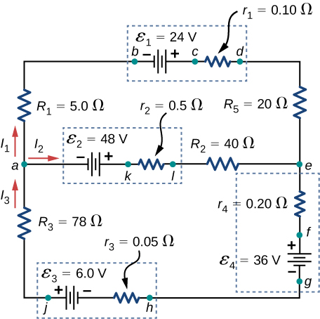
Apply the loop rule to Loop akledcba in the preceding problem.
Find the currents flowing in the circuit in the preceding problem. Explicitly show how you follow the steps in the Problem-Solving Strategy: Series and Parallel Resistors .
Consider the circuit shown below. (a) Find the current through each resistor. (b) Check the calculations by analyzing the power in the circuit.
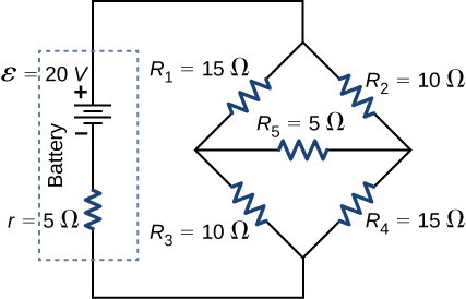
a.
;
b.
A flashing lamp in a Christmas earring is based on an RC discharge of a capacitor through its resistance. The effective duration of the flash is 0.250 s, during which it produces an average 0.500 W from an average 3.00 V. (a) What energy does it dissipate? (b) How much charge moves through the lamp? (c) Find the capacitance. (d) What is the resistance of the lamp? (Since average values are given for some quantities, the shape of the pulse profile is not needed.)
A capacitor charged to 450 V is discharged through a resistor. (a) Find the time constant. (b) Calculate the temperature increase of the resistor, given that its mass is 2.50 g and its specific heat is noting that most of the thermal energy is retained in the short time of the discharge. (c) Calculate the new resistance, assuming it is pure carbon. (d) Does this change in resistance seem significant?
a. 4.99 s; b. ; c. ; d. No, this change does not seem significant. It probably would not be noticed.
Some camera flashes use flash tubes that require a high voltage. They obtain a high voltage by charging capacitors in parallel and then internally changing the connections of the capacitors to place them in series. Consider a circuit that uses four AAA batteries connected in series to charge six 10-mF capacitors through an equivalent resistance of . The connections are then switched internally to place the capacitors in series. The capacitors discharge through a lamp with a resistance of . (a) What is the RC time constant and the initial current out of the batteries while they are connected in parallel? (b) How long does it take for the capacitors to charge to of the terminal voltages of the batteries? (c) What is the RC time constant and the initial current of the capacitors connected in series assuming it discharges at of full charge? (d) How long does it take the current to decrease to of the initial value?
Consider the circuit shown below. Each battery has an emf of 1.50 V and an internal resistance of (a) What is the current through the external resistor, which has a resistance of 10.00 ohms? (b) What is the terminal voltage of each battery?
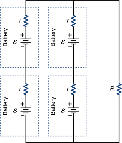
a. 0.273 A; b.
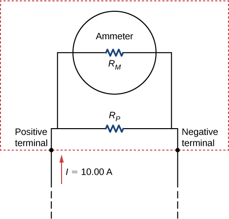
Analog meters use a galvanometer, which essentially consists of a coil of wire with a small resistance and a pointer with a scale attached. When current runs through the coil, the pointer turns; the amount the pointer turns is proportional to the amount of current running through the coil. Galvanometers can be used to make an ammeter if a resistor is placed in parallel with the galvanometer. Consider a galvanometer that has a resistance of and gives a full scale reading when a current runs through it. The galvanometer is to be used to make an ammeter that has a full scale reading of 10.00 A, as shown below. Recall that an ammeter is connected in series with the circuit of interest, so all 10 A must run through the meter. (a) What is the current through the parallel resistor in the meter? (b) What is the voltage across the parallel resistor? (c) What is the resistance of the parallel resistor?
Notification Switch
Would you like to follow the 'University physics volume 2' conversation and receive update notifications?

|
|

|
|

|
|

|
|

|
|
|
|
|
|
|
|

|
|

|
|

|