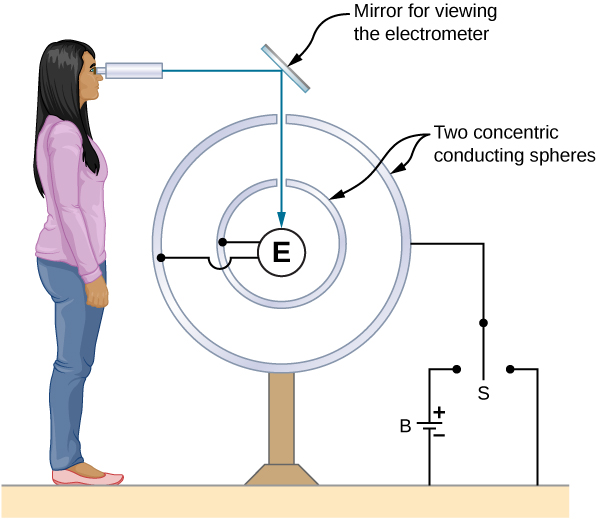
A representation of the apparatus used by Plimpton and Lawton. Any transfer of charge between the spheres is detected by the electrometer E.
The electric field at the surface of a conductor
If the electric field had a component parallel to the surface of a conductor, free charges on the surface would move, a situation contrary to the assumption of electrostatic equilibrium. Therefore, the electric field is always perpendicular to the surface of a conductor.
At any point just above the surface of a conductor, the surface charge density
and the magnitude of the electric field
E are related by
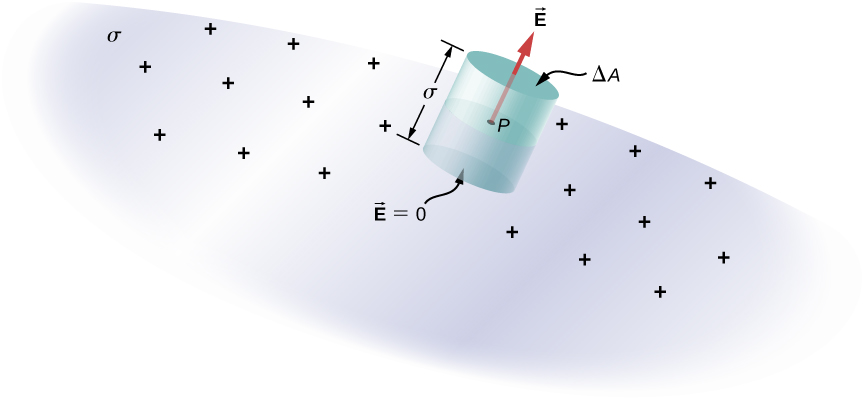
To see this, consider an infinitesimally small Gaussian cylinder that surrounds a point on the surface of the conductor, as in
[link] . The cylinder has one end face inside and one end face outside the surface. The height and cross-sectional area of the cylinder are
and
, respectively. The cylinder’s sides are perpendicular to the surface of the conductor, and its end faces are parallel to the surface. Because the cylinder is infinitesimally small, the charge density
is essentially constant over the surface enclosed, so the total charge inside the Gaussian cylinder is
. Now
E is perpendicular to the surface of the conductor outside the conductor and vanishes within it, because otherwise, the charges would accelerate, and we would not be in equilibrium. Electric flux therefore crosses only the outer end face of the Gaussian surface and may be written as
, since the cylinder is assumed to be small enough that
E is approximately constant over that area. From Gauss’ law,
Thus,
An infinitesimally small cylindrical Gaussian surface surrounds point
P , which is on the surface of the conductor. The field
is perpendicular to the surface of the conductor outside the conductor and vanishes within it.
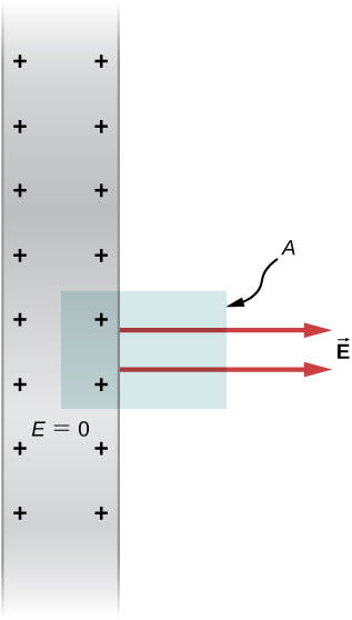
Electric field of a conducting plate
The infinite conducting plate in
[link] has a uniform surface charge density
. Use Gauss’ law to find the electric field outside the plate. Compare this result with that previously calculated directly.
A side view of an infinite conducting plate and Gaussian cylinder with cross-sectional area
A .
Strategy
For this case, we use a cylindrical Gaussian surface, a side view of which is shown.
Solution
The flux calculation is similar to that for an infinite sheet of charge from the previous chapter with one major exception: The left face of the Gaussian surface is inside the conductor where
so the total flux through the Gaussian surface is
EA rather than 2
EA . Then from Gauss’ law,
and the electric field outside the plate is
Significance
This result is in agreement with the result from the previous section, and consistent with the rule stated above.
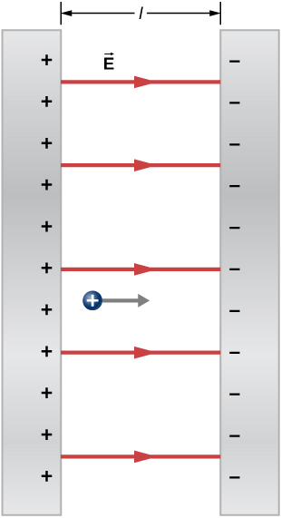
Electric field between oppositely charged parallel plates
Two large conducting plates carry equal and opposite charges, with a surface charge density
of magnitude
as shown in
[link] . The separation between the plates is
. What is the electric field between the plates?
The electric field between oppositely charged parallel plates. A test charge is released at the positive plate.
Strategy
Note that the electric field at the surface of one plate only depends on the charge on that plate. Thus, apply
with the given values.
Solution
The electric field is directed from the positive to the negative plate, as shown in the figure, and its magnitude is given by
Significance
This formula is applicable to more than just a plate. Furthermore, two-plate systems will be important later.