is the temperature dependence of the resistance of an object, where
is the original resistance (usually taken to be
and
R is the resistance after a temperature change
The color code gives the resistance of the resistor at a temperature of
.
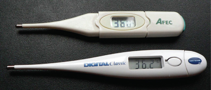
Numerous thermometers are based on the effect of temperature on resistance (
[link] ). One of the most common thermometers is based on the thermistor, a semiconductor crystal with a strong temperature dependence, the resistance of which is measured to obtain its temperature. The device is small, so that it quickly comes into thermal equilibrium with the part of a person it touches.
These familiar thermometers are based on the automated measurement of a thermistor’s temperature-dependent resistance.
Calculating resistance
Although caution must be used in applying
and
for temperature changes greater than
, for tungsten, the equations work reasonably well for very large temperature changes. A tungsten filament at
has a resistance of
. What would the resistance be if the temperature is increased to
?
Strategy
This is a straightforward application of
, since the original resistance of the filament is given as
and the temperature change is
.
Solution
The resistance of the hotter filament
R is obtained by entering known values into the above equation:
Significance
Notice that the resistance changes by more than a factor of 10 as the filament warms to the high temperature and the current through the filament depends on the resistance of the filament and the voltage applied. If the filament is used in an incandescent light bulb, the initial current through the filament when the bulb is first energized will be higher than the current after the filament reaches the operating temperature.
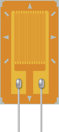
Check Your Understanding A strain gauge is an electrical device to measure strain, as shown below. It consists of a flexible, insulating backing that supports a conduction foil pattern. The resistance of the foil changes as the backing is stretched. How does the strain gauge resistance change? Is the strain gauge affected by temperature changes?
The foil pattern stretches as the backing stretches, and the foil tracks become longer and thinner. Since the resistance is calculated as
, the resistance increases as the foil tracks are stretched. When the temperature changes, so does the resistivity of the foil tracks, changing the resistance. One way to combat this is to use two strain gauges, one used as a reference and the other used to measure the strain. The two strain gauges are kept at a constant temperature
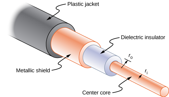
Long cables can sometimes act like antennas, picking up electronic noise, which are signals from other equipment and appliances. Coaxial cables are used for many applications that require this noise to be eliminated. For example, they can be found in the home in cable TV connections or other audiovisual connections. Coaxial cables consist of an inner conductor of radius
surrounded by a second, outer concentric conductor with radius
(
[link] ). The space between the two is normally filled with an insulator such as polyethylene plastic. A small amount of radial leakage current occurs between the two conductors. Determine the resistance of a coaxial cable of length
L .
Coaxial cables consist of two concentric conductors separated by insulation. They are often used in cable TV or other audiovisual connections.
Strategy
We cannot use the equation
directly. Instead, we look at concentric cylindrical shells, with thickness
dr , and integrate.
Solution
We first find an expression for
dR and then integrate from
to
,
Significance
The resistance of a coaxial cable depends on its length, the inner and outer radii, and the resistivity of the material separating the two conductors. Since this resistance is not infinite, a small leakage current occurs between the two conductors. This leakage current leads to the attenuation (or weakening) of the signal being sent through the cable.