<< Chapter < Page Chapter >> Page >
By the end of the section, you will be able to:
  • Explain why power plants transmit electricity at high voltages and low currents and how they do this
  • Develop relationships among current, voltage, and the number of windings in step-up and step-down transformers

Although ac electric power is produced at relatively low voltages, it is sent through transmission lines at very high voltages (as high as 500 kV). The same power can be transmitted at different voltages because power is the product I rms V rms . (For simplicity, we ignore the phase factor cos ϕ . ) A particular power requirement can therefore be met with a low voltage and a high current or with a high voltage and a low current. The advantage of the high-voltage/low-current choice is that it results in lower I rms 2 R ohmic losses in the transmission lines, which can be significant in lines that are many kilometers long ( [link] ).

Figure shows a power plant on the left. This is connected to a step up transformer through a 12 kV line. The transformer is connected to a high voltage transmission line of 400 kV. This is connected to a step down transformer at a substation. From here, a 13 kV line goes to a step down transformer on an electric pole. From here a 240 V line goes to a house.
The rms voltage from a power plant eventually needs to be stepped down from 12 kV to 240 V so that it can be safely introduced into a home. A high-voltage transmission line allows a low current to be transmitted via a substation over long distances.

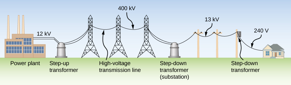
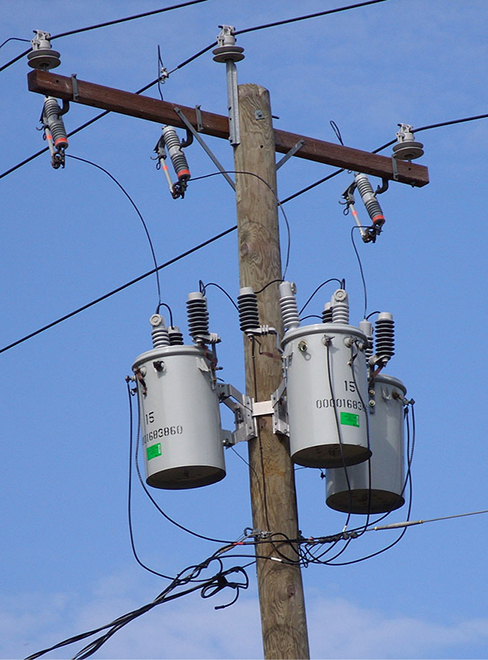
Typically, the alternating emfs produced at power plants are “stepped up” to very high voltages before being transmitted through power lines; then, they must be “stepped down” to relatively safe values (110 or 220 V rms) before they are introduced into homes. The device that transforms voltages from one value to another using induction is the transformer    ( [link] ).

Photograph of transformers on an electric pole. There are three transformers, each encased in a cylindrical container.
Transformers are used to step down the high voltages in transmission lines to the 110 to 220 V used in homes. (credit: modification of work by “Fortyseven”/Flickr)

As [link] illustrates, a transformer basically consists of two separated coils, or windings, wrapped around a soft iron core. The primary winding has N P loops, or turns, and is connected to an alternating voltage v P ( t ) . The secondary winding has N S turns and is connected to a load resistor R S . We assume the ideal case for which all magnetic field lines are confined to the core so that the same magnetic flux permeates each turn of both the primary and the secondary windings. We also neglect energy losses to magnetic hysteresis, to ohmic heating in the windings, and to ohmic heating of the induced eddy currents in the core. A good transformer can have losses as low as 1% of the transmitted power, so this is not a bad assumption.

Figure shows a soft iron core in the center. This is in the form of a rectangular ring. There are windings on its left arm, connected to a voltage source. These are labeled N subscript p turns. The current through them is i subscript p parentheses t parentheses. The voltage across two ends of the windings is v subscript p parentheses t parentheses. The windings on the right arm of the core are connected to a resistor R subscript s. The windings are labeled N subscript s turns. These are more in number than the windings on the left arm. The current in the right circuit is i subscript s parentheses t parentheses. The voltage across the windings is v subscript s parentheses t parentheses. The current in the left circuit flows into the windings from the top. The current in the right circuit flows out of the winding from the top.
A step-up transformer (more turns in the secondary winding than in the primary winding). The two windings are wrapped around a soft iron core.

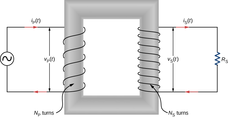
To analyze the transformer circuit, we first consider the primary winding. The input voltage v P ( t ) is equal to the potential difference induced across the primary winding. From Faraday’s law, the induced potential difference is N P ( d Φ / d t ) , where Φ is the flux through one turn of the primary winding. Thus,

v P ( t ) = N P d Φ d t .

Similarly, the output voltage v S ( t ) delivered to the load resistor must equal the potential difference induced across the secondary winding. Since the transformer is ideal, the flux through every turn of the secondary winding is also Φ , and

Practice Key Terms 4

Get Jobilize Job Search Mobile App in your pocket Now!

Get it on Google Play Download on the App Store Now


Source:  OpenStax, University physics volume 2. OpenStax CNX. Oct 06, 2016 Download for free at http://cnx.org/content/col12074/1.3
Google Play and the Google Play logo are trademarks of Google Inc.

Notification Switch

Would you like to follow the 'University physics volume 2' conversation and receive update notifications?

Ask