<< Chapter < Page Chapter >> Page >
By the end of the section, you will be able to:
  • Describe how average power from an ac circuit can be written in terms of peak current and voltage and of rms current and voltage
  • Determine the relationship between the phase angle of the current and voltage and the average power, known as the power factor

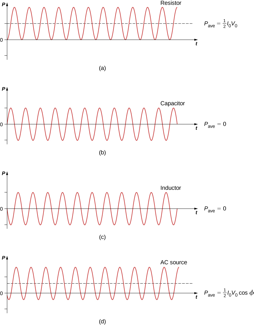
A circuit element dissipates or produces power according to P = I V , where I is the current through the element and V is the voltage across it. Since the current and the voltage both depend on time in an ac circuit, the instantaneous power p ( t ) = i ( t ) v ( t ) is also time dependent. A plot of p ( t ) for various circuit elements is shown in [link] . For a resistor, i ( t ) and v ( t ) are in phase and therefore always have the same sign (see [link] ). For a capacitor or inductor, the relative signs of i ( t ) and v ( t ) vary over a cycle due to their phase differences (see [link] and [link] ). Consequently, p ( t ) is positive at some times and negative at others, indicating that capacitive and inductive elements produce power at some instants and absorb it at others.

Figures a through d show sine waves on graphs of P versus t. All have the same amplitude and frequency. Figure a is labeled resistor. P bar is equal to half I0 V0. The sine wave is above the x axis, with the minimum y value being 0. It starts from a trough. Figure b is labeled capacitor. P bar is equal to 0. The equilibrium position of the sine wave is along the x axis. It starts at equilibrium with a positive slope. Figure c is labeled inductor. P bar is equal to 0. The equilibrium position of the sine wave is along the x axis. It starts at equilibrium with a negative slope. Figure d is labeled AC source. P bar is equal to half I0 V0 cos phi. The equilibrium position of the sine wave is above the x axis, with the minimum y-value of the wave being negative.
Graph of instantaneous power for various circuit elements. (a) For the resistor, P ave = I 0 V 0 / 2 , whereas for (b) the capacitor and (c) the inductor, P ave = 0 . (d) For the source, P ave = I 0 V 0 ( cos ϕ ) / 2 , which may be positive, negative, or zero, depending on ϕ .

Because instantaneous power varies in both magnitude and sign over a cycle, it seldom has any practical importance. What we’re almost always concerned with is the power averaged over time, which we refer to as the average power    . It is defined by the time average of the instantaneous power over one cycle:

P ave = 1 T 0 T p ( t ) d t ,

where T = 2 π / ω is the period of the oscillations. With the substitutions v ( t ) = V 0 sin ω t and i ( t ) = I 0 sin ( ω t ϕ ) , this integral becomes

P ave = I 0 V 0 T 0 T sin ( ω t ϕ ) sin ω t d t .

Using the trigonometric relation sin ( A B ) = sin A cos B sin B cos A , we obtain

P ave = I 0 V 0 cos ϕ T 0 T sin ω t d t I 0 V 0 sin ϕ T 0 T sin 2 ω t cos ω t d t .

Evaluation of these two integrals yields

1 T 0 T sin 2 ω t d t = 1 2

and

1 T 0 T sin ω t cos ω t d t = 0 .

Hence, the average power associated with a circuit element is given by

P ave = 1 2 I 0 V 0 cos ϕ .

In engineering applications, cos ϕ is known as the power factor    , which is the amount by which the power delivered in the circuit is less than the theoretical maximum of the circuit due to voltage and current being out of phase. For a resistor, ϕ = 0 , so the average power dissipated is

P ave = 1 2 I 0 V 0 .

A comparison of p ( t ) and P ave is shown in [link] (d). To make P ave = ( 1 / 2 ) I 0 V 0 look like its dc counterpart, we use the rms values I rms and V rms of the current and the voltage. By definition, these are

I rms = i ave 2 and V rms = v ave 2 ,

where

i ave 2 = 1 T 0 T i 2 ( t ) d t and  v ave 2 = 1 T 0 T v 2 ( t ) d t .

With i ( t ) = I 0 sin ( ω t ϕ ) and v ( t ) = V 0 sin ω t , we obtain

I rms = 1 2 I 0 and V rms = 1 2 V 0 .

We may then write for the average power dissipated by a resistor,

P ave = 1 2 I 0 V 0 = I rms V rms = I rms 2 R .

This equation further emphasizes why the rms value is chosen in discussion rather than peak values. Both equations for average power are correct for [link] , but the rms values in the formula give a cleaner representation, so the extra factor of 1/2 is not necessary.

Practice Key Terms 2

Get Jobilize Job Search Mobile App in your pocket Now!

Get it on Google Play Download on the App Store Now


Source:  OpenStax, University physics volume 2. OpenStax CNX. Oct 06, 2016 Download for free at http://cnx.org/content/col12074/1.3
Google Play and the Google Play logo are trademarks of Google Inc.

Notification Switch

Would you like to follow the 'University physics volume 2' conversation and receive update notifications?

Ask