

| << Chapter < Page | Chapter >> Page > |
It is worth noting that both capacitors and inductors store energy, in their electric and magnetic fields, respectively. A circuit containing both an inductor ( L ) and a capacitor ( C ) can oscillate without a source of emf by shifting the energy stored in the circuit between the electric and magnetic fields. Thus, the concepts we develop in this section are directly applicable to the exchange of energy between the electric and magnetic fields in electromagnetic waves, or light. We start with an idealized circuit of zero resistance that contains an inductor and a capacitor, an LC circuit .
An LC circuit is shown in [link] . If the capacitor contains a charge before the switch is closed, then all the energy of the circuit is initially stored in the electric field of the capacitor ( [link] (a)). This energy is
When the switch is closed, the capacitor begins to discharge, producing a current in the circuit. The current, in turn, creates a magnetic field in the inductor. The net effect of this process is a transfer of energy from the capacitor, with its diminishing electric field, to the inductor, with its increasing magnetic field.
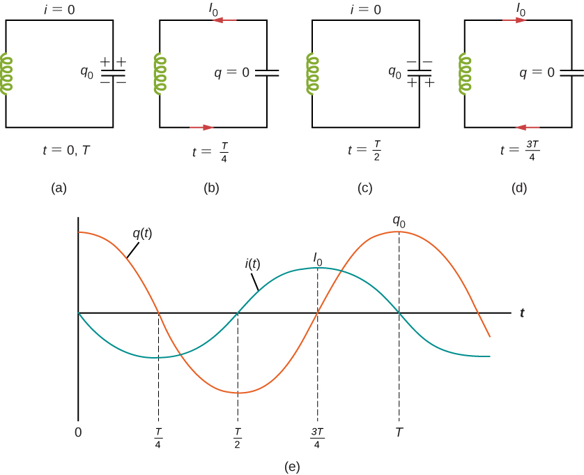
In [link] (b), the capacitor is completely discharged and all the energy is stored in the magnetic field of the inductor. At this instant, the current is at its maximum value and the energy in the inductor is
Since there is no resistance in the circuit, no energy is lost through Joule heating; thus, the maximum energy stored in the capacitor is equal to the maximum energy stored at a later time in the inductor:
At an arbitrary time when the capacitor charge is q(t) and the current is i(t) , the total energy U in the circuit is given by
Because there is no energy dissipation,
After reaching its maximum the current i(t) continues to transport charge between the capacitor plates, thereby recharging the capacitor. Since the inductor resists a change in current, current continues to flow, even though the capacitor is discharged. This continued current causes the capacitor to charge with opposite polarity. The electric field of the capacitor increases while the magnetic field of the inductor diminishes, and the overall effect is a transfer of energy from the inductor back to the capacitor. From the law of energy conservation, the maximum charge that the capacitor re-acquires is However, as [link] (c) shows, the capacitor plates are charged opposite to what they were initially.
When fully charged, the capacitor once again transfers its energy to the inductor until it is again completely discharged, as shown in [link] (d). Then, in the last part of this cyclic process, energy flows back to the capacitor, and the initial state of the circuit is restored.
Notification Switch
Would you like to follow the 'University physics volume 2' conversation and receive update notifications?

|
|

|
|

|
|

|
|

|
|

|
|

|
|

|
|
|
|
|

|