

| << Chapter < Page | Chapter >> Page > |
Check Your Understanding Verify that RC and L/R have the dimensions of time.
Check Your Understanding (a) If the current in the circuit of in [link] (b) increases to of its final value after 5.0 s, what is the inductive time constant? (b) If , what is the value of the self-inductance? (c) If the resistor is replaced with a resister, what is the time taken for the current to reach of its final value?
a. 2.2 s; b. 43 H; c. 1.0 s
Check Your Understanding For the circuit of in [link] (b), show that when steady state is reached, the difference in the total energies produced by the battery and dissipated in the resistor is equal to the energy stored in the magnetic field of the coil.
Use Lenz’s law to explain why the initial current in the RL circuit of [link] (b) is zero.
As current flows through the inductor, there is a back current by Lenz’s law that is created to keep the net current at zero amps, the initial current.
When the current in the RL circuit of [link] (b) reaches its final value what is the voltage across the inductor? Across the resistor?
Does the time required for the current in an RL circuit to reach any fraction of its steady-state value depend on the emf of the battery?
no
An inductor is connected across the terminals of a battery. Does the current that eventually flows through the inductor depend on the internal resistance of the battery? Does the time required for the current to reach its final value depend on this resistance?
At what time is the voltage across the inductor of the RL circuit of [link] (b) a maximum?
At , or when the switch is first thrown.
In the simple RL circuit of [link] (b), can the emf induced across the inductor ever be greater than the emf of the battery used to produce the current?
If the emf of the battery of [link] (b) is reduced by a factor of 2, by how much does the steady-state energy stored in the magnetic field of the inductor change?
1/4
A steady current flows through a circuit with a large inductive time constant. When a switch in the circuit is opened, a large spark occurs across the terminals of the switch. Explain.
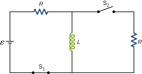
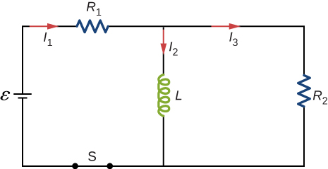
Describe how the currents through shown below vary with time after switch S is closed.

Initially, and , and after a long time has passed, and .
Discuss possible practical applications of RL circuits.
In [link] , , , and . Determine (a) the time constant of the circuit, (b) the initial current through the resistor, (c) the final current through the resistor, (d) the current through the resistor when and (e) the voltages across the inductor and the resistor when
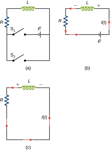
For the circuit shown below, , and . After steady state is reached with closed and open, is closed and immediately thereafter is opened. Determine (a) the current through L at , (b) the current through L at , and (c) the voltages across L and R at .
a. 4.0 A; b. 2.4 A; c. on R : ; on L :
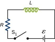
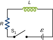
The current in the RL circuit shown here increases to of its steady-state value in 2.0 s. What is the time constant of the circuit?
How long after switch is thrown does it take the current in the circuit shown to reach half its maximum value? Express your answer in terms of the time constant of the circuit.
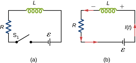
Examine the circuit shown below in part (a). Determine dI/dt at the instant after the switch is thrown in the circuit of (a), thereby producing the circuit of (b). Show that if I were to continue to increase at this initial rate, it would reach its maximum in one time constant.
The current in the RL circuit shown below reaches half its maximum value in 1.75 ms after the switch is thrown. Determine (a) the time constant of the circuit and (b) the resistance of the circuit if .
a. 2.52 ms; b.
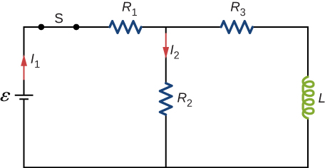
Consider the circuit shown below. Find when (a) the switch S is first closed, (b) after the currents have reached steady-state values, and (c) at the instant the switch is reopened (after being closed for a long time).
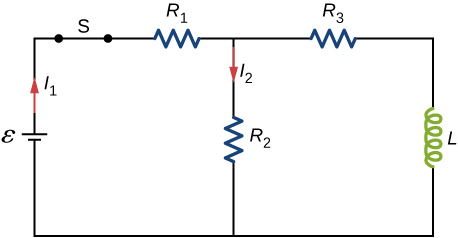
For the circuit shown below, , and . Find the values of (a) immediately after switch S is closed, (b) a long time after S is closed, (c) immediately after S is reopened, and (d) a long time after S is reopened.
a. ; b. ; c. ; d.
For the circuit shown below, find the current through the inductor after the switch is reopened.
Show that for the circuit shown below, the initial energy stored in the inductor, , is equal to the total energy eventually dissipated in the resistor, .

proof
Notification Switch
Would you like to follow the 'University physics volume 2' conversation and receive update notifications?

|
|

|
|
|
|
|

|
|

|
|

|
|

|
|

|
|

|
|

|