The time constant
also tells us how quickly the induced voltage decays. At
the magnitude of the induced voltage is
The voltage across the inductor therefore drops to about
of its initial value after one time constant. The shorter the time constant
the more rapidly the voltage decreases.
After enough time has elapsed so that the current has essentially reached its final value, the positions of the switches in
[link] (a) are reversed, giving us the circuit in part (c). At
the current in the circuit is
With Kirchhoff’s loop rule, we obtain
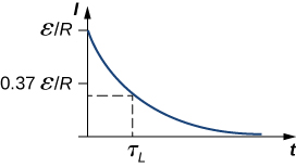
The solution to this equation is similar to the solution of the equation for a discharging capacitor, with similar substitutions. The current at time
t is then
The current starts at
and decreases with time as the energy stored in the inductor is depleted (
[link] ).
The time dependence of the voltage across the inductor can be determined from
This voltage is initially
, and it decays to zero like the current. The energy stored in the magnetic field of the inductor,
also decreases exponentially with time, as it is dissipated by Joule heating in the resistance of the circuit.
Time variation of electric current in the
RL circuit of
[link] (c). The induced voltage across the coil also decays exponentially.
An
RL Circuit with a source of emf
In the circuit of
[link] (a), let
With
closed and
open (
[link] (b)), (a) what is the time constant of the circuit? (b) What are the current in the circuit and the magnitude of the induced emf across the inductor at
, and as
?
Strategy
The time constant for an inductor and resistor in a series circuit is calculated using
[link] . The current through and voltage across the inductor are calculated by the scenarios detailed from
[link] and
[link] .
Solution
The inductive time constant is
The current in the circuit of
[link] (b) increases according to
[link] :
At
At
and
we have, respectively,
and
From
[link] , the magnitude of the induced emf decays as
we obtain
Significance
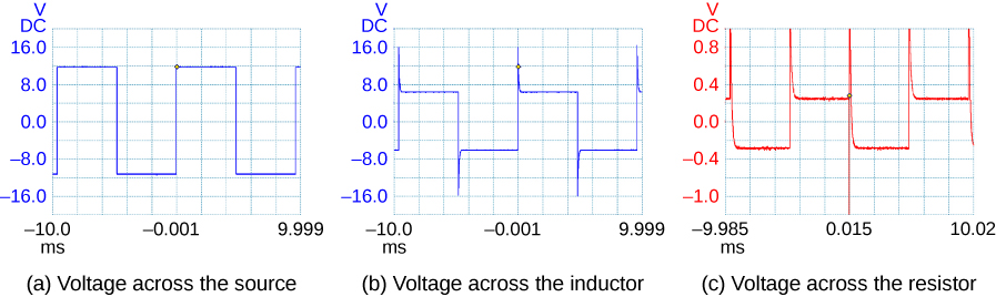
If the time of the measurement were much larger than the time constant, we would not see the decay or growth of the voltage across the inductor or resistor. The circuit would quickly reach the asymptotic values for both of these. See
[link] .
A generator in an
RL circuit produces a square-pulse output in which the voltage oscillates between zero and some set value. These oscilloscope traces show (a) the voltage across the source; (b) the voltage across the inductor; (c) the voltage across the resistor.
After the current in the
RL circuit of
[link] has reached its final value, the positions of the switches are reversed so that the circuit becomes the one shown in
[link] (c). (a) How long does it take the current to drop to half its initial value? (b) How long does it take before the energy stored in the inductor is reduced to
of its maximum value?
Strategy
The current in the inductor will now decrease as the resistor dissipates this energy. Therefore, the current falls as an exponential decay. We can also use that same relationship as a substitution for the energy in an inductor formula to find how the energy decreases at different time intervals.
Solution
With the switches reversed, the current decreases according to
At a time
t when the current is one-half its initial value, we have
and
where we have used the inductive time constant found in
[link] .
The energy stored in the inductor is given by
If the energy drops to
of its initial value at a time
t , we have
Upon canceling terms and taking the natural logarithm of both sides, we obtain
so
Since
, the time it takes for the energy stored in the inductor to decrease to
of its initial value is
Significance
This calculation only works if the circuit is at maximum current in situation (b) prior to this new situation. Otherwise, we start with a lower initial current, which will decay by the same relationship.