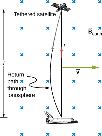
Motional emf as electrical power conversion for the space shuttle was the motivation for the tethered satellite experiment. A 5-kV emf was predicted to be induced in the 20-km tether while moving at orbital speed in Earth’s magnetic field. The circuit is completed by a return path through the stationary ionosphere.
Calculating the large motional emf of an object in orbit
Calculate the motional emf induced along a 20.0-km conductor moving at an orbital speed of 7.80 km/s perpendicular to Earth’s
magnetic field.
Strategy
This is a great example of using the equation motional
Solution
Entering the given values into
gives
Significance
The value obtained is greater than the 5-kV measured voltage for the shuttle experiment, since the actual orbital motion of the tether is not perpendicular to Earth’s field. The 7.80-kV value is the maximum emf obtained when
and so
Part (a) of
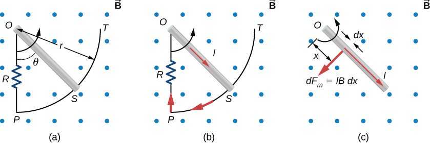
[link] shows a metal rod
OS that is rotating in a horizontal plane around point
O . The rod slides along a wire that forms a circular arc
PST of radius
r . The system is in a constant magnetic field
that is directed out of the page. (a) If you rotate the rod at a constant angular velocity
, what is the current
I in the closed loop
OPSO ? Assume that the resistor
R furnishes all of the resistance in the closed loop. (b) Calculate the work per unit time that you do while rotating the rod and show that it is equal to the power dissipated in the resistor.
(a) The end of a rotating metal rod slides along a circular wire in a horizontal plane. (b) The induced current in the rod. (c) The magnetic force on an infinitesimal current segment.
Strategy
The magnetic flux is the magnetic field times the area of the quarter circle or
When finding the emf through Faraday’s law, all variables are constant in time but
, with
To calculate the work per unit time, we know this is related to the torque times the angular velocity. The torque is calculated by knowing the force on a rod and integrating it over the length of the rod.
Solution
From geometry, the area of the loop
OPSO is
Hence, the magnetic flux through the loop is
Differentiating with respect to time and using
we have
When divided by the resistance
R of the loop, this yields for the magnitude of the induced current
As
increases, so does the flux through the loop due to
To counteract this increase, the magnetic field due to the induced current must be directed into the page in the region enclosed by the loop. Therefore, as part (b) of
[link] illustrates, the current circulates clockwise.
You rotate the rod by exerting a torque on it. Since the rod rotates at constant angular velocity, this torque is equal and opposite to the torque exerted on the current in the rod by the original magnetic field. The magnetic force on the infinitesimal segment of length
dx shown in part (c) of
[link] is
so the magnetic torque on this segment is
The net magnetic torque on the rod is then
The torque
that you exert on the rod is equal and opposite to
and the work that you do when the rod rotates through an angle
is
Hence, the work per unit time that you do on the rod is
where we have substituted for
I . The power dissipated in the resister is
, which can be written as
Therefore, we see that
Hence, the power dissipated in the resistor is equal to the work per unit time done in rotating the rod.