<< Chapter < Page Chapter >> Page >
The figure shows a loop with positive terminal of voltage source of 12 V connected to three resistors of 1 Ω, 2 Ω and 3 Ω in series.
A simple loop with no junctions. Kirchhoff’s loop rule states that the algebraic sum of the voltage differences is equal to zero.

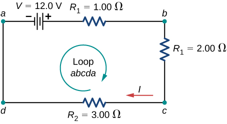
The circuit consists of a voltage source and three external load resistors. The labels a , b , c , and d serve as references, and have no other significance. The usefulness of these labels will become apparent soon. The loop is designated as Loop abcda , and the labels help keep track of the voltage differences as we travel around the circuit. Start at point a and travel to point b . The voltage of the voltage source is added to the equation and the potential drop of the resistor R 1 is subtracted. From point b to c , the potential drop across R 2 is subtracted. From c to d , the potential drop across R 3 is subtracted. From points d to a , nothing is done because there are no components.

[link] shows a graph of the voltage as we travel around the loop. Voltage increases as we cross the battery, whereas voltage decreases as we travel across a resistor. The potential drop    , or change in the electric potential, is equal to the current through the resistor times the resistance of the resistor. Since the wires have negligible resistance, the voltage remains constant as we cross the wires connecting the components.

The graph shows voltage at different points of a closed loop circuit with a voltage source and three resistances. The points are shown on x-axis and voltages on y-axis.
A voltage graph as we travel around the circuit. The voltage increases as we cross the battery and decreases as we cross each resistor. Since the resistance of the wire is quite small, we assume that the voltage remains constant as we cross the wires connecting the components.

Then Kirchhoff’s loop rule states

V I R 1 I R 2 I R 3 = 0 .

The loop equation can be used to find the current through the loop:

I = V R 1 + R 2 + R 2 = 12.00 V 1.00 Ω + 2.00 Ω + 3.00 Ω = 2.00 A .

This loop could have been analyzed using the previous methods, but we will demonstrate the power of Kirchhoff’s method in the next section.

Applying kirchhoff’s rules

By applying Kirchhoff’s rules, we generate a set of linear equations that allow us to find the unknown values in circuits. These may be currents, voltages, or resistances. Each time a rule is applied, it produces an equation. If there are as many independent equations as unknowns, then the problem can be solved.

Using Kirchhoff’s method of analysis requires several steps, as listed in the following procedure.

Problem-solving strategy: kirchhoff’s rules

  1. Label points in the circuit diagram using lowercase letters a , b , c , …. These labels simply help with orientation.
  2. Locate the junctions in the circuit. The junctions are points where three or more wires connect. Label each junction with the currents and directions into and out of it. Make sure at least one current points into the junction and at least one current points out of the junction.
  3. Choose the loops in the circuit. Every component must be contained in at least one loop, but a component may be contained in more than one loop.
  4. Apply the junction rule. Again, some junctions should not be included in the analysis. You need only use enough nodes to include every current.
  5. Apply the loop rule. Use the map in [link] .
Part a shows voltage difference across a resistor when direction of travel is same as current direction. Part b shows voltage difference across a resistor when direction of travel is opposite to current direction. Part c shows voltage difference across a voltage source when direction of travel is same as current direction. Part d shows voltage difference across a voltage source when direction of travel is opposite to current direction.
Each of these resistors and voltage sources is traversed from a to b . (a) When moving across a resistor in the same direction as the current flow, subtract the potential drop. (b) When moving across a resistor in the opposite direction as the current flow, add the potential drop. (c) When moving across a voltage source from the negative terminal to the positive terminal, add the potential drop. (d) When moving across a voltage source from the positive terminal to the negative terminal, subtract the potential drop.
Practice Key Terms 3

Get Jobilize Job Search Mobile App in your pocket Now!

Get it on Google Play Download on the App Store Now


Source:  OpenStax, University physics volume 2. OpenStax CNX. Oct 06, 2016 Download for free at http://cnx.org/content/col12074/1.3
Google Play and the Google Play logo are trademarks of Google Inc.

Notification Switch

Would you like to follow the 'University physics volume 2' conversation and receive update notifications?

Ask