

| << Chapter < Page | Chapter >> Page > |
Check Your Understanding Some strings of miniature holiday lights are made to short out when a bulb burns out. The device that causes the short is called a shunt, which allows current to flow around the open circuit. A “short” is like putting a piece of wire across the component. The bulbs are usually grouped in series of nine bulbs. If too many bulbs burn out, the shunts eventually open. What causes this?
The equivalent resistance of nine bulbs connected in series is 9 R . The current is If one bulb burns out, the equivalent resistance is 8 R , and the voltage does not change, but the current increases As more bulbs burn out, the current becomes even higher. Eventually, the current becomes too high, burning out the shunt.
Let’s briefly summarize the major features of resistors in series:
[link] shows resistors in parallel, wired to a voltage source. Resistors are in parallel when one end of all the resistors are connected by a continuous wire of negligible resistance and the other end of all the resistors are also connected to one another through a continuous wire of negligible resistance. The potential drop across each resistor is the same. Current through each resistor can be found using Ohm’s law where the voltage is constant across each resistor. For example, an automobile’s headlights, radio, and other systems are wired in parallel, so that each subsystem utilizes the full voltage of the source and can operate completely independently. The same is true of the wiring in your house or any building.
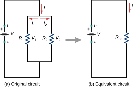
The current flowing from the voltage source in [link] depends on the voltage supplied by the voltage source and the equivalent resistance of the circuit. In this case, the current flows from the voltage source and enters a junction, or node, where the circuit splits flowing through resistors and . As the charges flow from the battery, some go through resistor and some flow through resistor The sum of the currents flowing into a junction must be equal to the sum of the currents flowing out of the junction:
This equation is referred to as Kirchhoff’s junction rule and will be discussed in detail in the next section. In [link] , the junction rule gives . There are two loops in this circuit, which leads to the equations and . Note the voltage across the resistors in parallel are the same and the current is additive:
Generalizing to any number of N resistors, the equivalent resistance of a parallel connection is related to the individual resistances by
Notification Switch
Would you like to follow the 'University physics volume 2' conversation and receive update notifications?

|
|

|
|

|
|

|
|

|
|

|
|

|
|

|
|

|
|

|