

| << Chapter < Page | Chapter >> Page > |
The operational amplifier is a special kind of voltage amplifier which is made from a handful of bipolar or field effect transistors. Operational amplifiers are usually called op-amps for short. They are used extensively in all kinds of audio equipment (amplifiers, mixers and so on) and in instrumentation. They also have many other uses in other circuits - for example comparing voltages from sensors.
Operational amplifiers are supplied on Integrated Circuits (I.C.s). The most famous operational amplifier I.C. is numbered 741 and contains a single operational amplifier on an integrated circuit (`chip') with eight terminals. Other varieties can be bought, and you can get a single integrated circuit with two or four `741'-type operational amplifiers on it.
The symbol for an op-amp is shown in [link] . The operational amplifier has two input terminals and one output terminal. The voltage of the output terminal is proportional to the difference in voltage between the two input terminals. The output terminal is on the right (at the sharp point of the triangle). The two input terminals are drawn on the left. One input terminal (labelled with a on diagrams) is called the non-inverting input . The other input terminal (labelled ) is called the inverting input . The labels and have nothing to do with the way in which the operational amplifier is connected to the power supply. Operational amplifiers must be connected to the power supply, but this is taken for granted when circuit diagrams are drawn, and these connections are not shown on circuit diagrams. Usually, when drawing electronic circuits, `0V' is taken to mean the negative terminal of the power supply. This is not the case with op-amps. For an op-amp, `0V' refers to the voltage midway between the and of the supply.
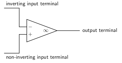
The output voltage of the amplifier is given by the formula where is a constant called the open loop gain , and and are the voltages of the two input terminals. That said, the output voltage can not be less than the voltage of the negative terminal of the battery supplying it or higher than the positive terminal of the battery supplying it. You will notice that is positive if and negative if . This is why the input is called the inverting input: raising its voltage causes the output voltage to drop .
The input resistance of an operational amplifier is very high. This means that very little current flows into the input terminals during operation.
If all of the transistors in the operational amplifier were identical then the output voltage would be zero if the two inputs were at equal voltages. In practice this is not quite the case, and for sensitive work a trimming potentiometer is connected. This is adjusted until the op-amp is zeroed correctly.
Simple operational amplifiers require the trimming potentiometer to be built into the circuit containing them, and an example is shown in [link] . Other operational amplifier designs incorporate separate terminals for the trimming potentiometer. These special terminals are labelled offset on the manufacturer's diagram. The exact method of connecting the potentiometer to the offset terminals can depend on the design of the operational amplifier, and you need to refer to the manufacturer's data sheet for details of which potentiometer to use and how to connect it.
For most commercially produced operational amplifiers (known as op-amps for short), the open loop gain is very large and does not stay constant. Values of 100 000 are typical. Usually a designer would want an amplifier with a stable gain of smaller value, and builds the operational amplifier into a circuit like the one in [link] .

Notification Switch
Would you like to follow the 'Siyavula textbooks: grade 12 physical science' conversation and receive update notifications?

|
|

|
|

|
|

|
|
|
|
|

|
|

|
|

|
|

|
|
|
|