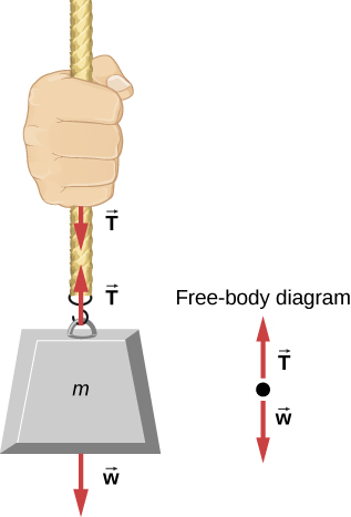
Consider a person holding a mass on a rope, as shown in
[link] . If the 5.00-kg mass in the figure is stationary, then its acceleration is zero and the net force is zero. The only external forces acting on the mass are its weight and the tension supplied by the rope. Thus,
where
T and
w are the magnitudes of the tension and weight, respectively, and their signs indicate direction, with up being positive. As we proved using Newton’s second law, the tension equals the weight of the supported mass:
Thus, for a 5.00-kg mass (neglecting the mass of the rope), we see that
If we cut the rope and insert a spring, the spring would extend a length corresponding to a force of 49.0 N, providing a direct observation and measure of the tension force in the rope.
When a perfectly flexible connector (one requiring no force to bend it) such as this rope transmits a force
that force must be parallel to the length of the rope, as shown. By Newton’s third law, the rope pulls with equal force but in opposite directions on the hand and the supported mass (neglecting the weight of the rope). The rope is the medium that carries the equal and opposite forces between the two objects. The tension anywhere in the rope between the hand and the mass is equal. Once you have determined the tension in one location, you have determined the tension at all locations along the rope.
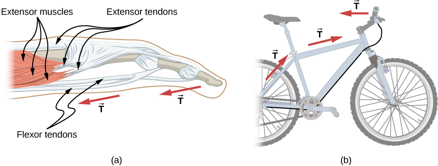
Flexible connectors are often used to transmit forces around corners, such as in a hospital traction system, a tendon, or a bicycle brake cable. If there is no friction, the tension transmission is undiminished; only its direction changes, and it is always parallel to the flexible connector, as shown in
[link] .
(a) Tendons in the finger carry force
T from the muscles to other parts of the finger, usually changing the force’s direction but not its magnitude (the tendons are relatively friction free). (b) The brake cable on a bicycle carries the tension
T from the brake lever on the handlebars to the brake mechanism. Again, the direction but not the magnitude of
T is changed.
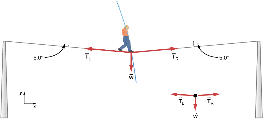
What is the tension in a tightrope?
Calculate the tension in the wire supporting the 70.0-kg tightrope walker shown in
[link] .
The weight of a tightrope walker causes a wire to sag by
. The system of interest is the point in the wire at which the tightrope walker is standing.
Strategy
As you can see in
[link] , the wire is bent under the person’s weight. Thus, the tension on either side of the person has an upward component that can support his weight. As usual, forces are vectors represented pictorially by arrows that have the same direction as the forces and lengths proportional to their magnitudes. The system is the tightrope walker, and the only external forces acting on him are his weight
and the two tensions
(left tension) and
(right tension). It is reasonable to neglect the weight of the wire. The net external force is zero, because the system is static. We can use trigonometry to find the tensions. One conclusion is possible at the outset—we can see from
[link] (b) that the magnitudes of the tensions
and
must be equal. We know this because there is no horizontal acceleration in the rope and the only forces acting to the left and right are
and
. Thus, the magnitude of those horizontal components of the forces must be equal so that they cancel each other out.