<< Chapter < Page Chapter >> Page >
Δ p = Δ p top = Δ p bottom = Δ p everywhere .

Pascal’s Barrel is a great demonstration of Pascal’s principle. Watch a simulation of Pascal’s 1646 experiment, in which he demonstrated the effects of changing pressure in a fluid.

Applications of pascal’s principle and hydraulic systems

Hydraulic systems are used to operate automotive brakes, hydraulic jacks, and numerous other mechanical systems ( [link] ).

A schematic drawing of a hydraulic system with two fluid-filled cylinders, capped with pistons and connected by a tube. A downward force F1 on the left piston with the surface area A1 creates a change in pressure that results in an upward force F2on the right piston with the surface area A2. Surface area A2 is larger than the surface area A1.
A typical hydraulic system with two fluid-filled cylinders, capped with pistons and connected by a tube called a hydraulic line. A downward force F 1 on the left piston creates a change in pressure that is transmitted undiminished to all parts of the enclosed fluid. This results in an upward force F 2 on the right piston that is larger than F 1 because the right piston has a larger surface area.

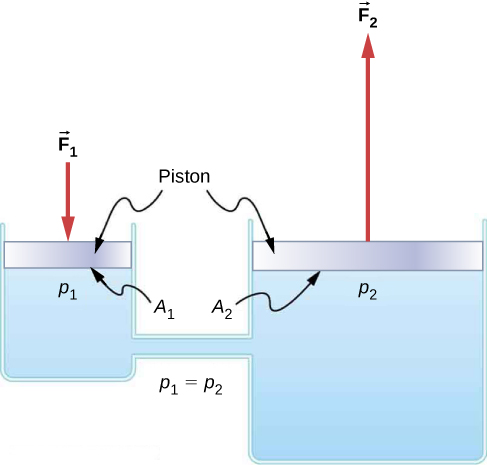
We can derive a relationship between the forces in this simple hydraulic system by applying Pascal’s principle. Note first that the two pistons in the system are at the same height, so there is no difference in pressure due to a difference in depth. The pressure due to F 1 acting on area A 1 is simply

p 1 = F 1 A 1 , as defined by p = F A .

According to Pascal’s principle, this pressure is transmitted undiminished throughout the fluid and to all walls of the container. Thus, a pressure p 2 is felt at the other piston that is equal to p 1 . That is, p 1 = p 2 . However, since p 2 = F 2 / A 2 , we see that

F 1 A 1 = F 2 A 2 .

This equation relates the ratios of force to area in any hydraulic system, provided that the pistons are at the same vertical height and that friction in the system is negligible.

Hydraulic systems can increase or decrease the force applied to them. To make the force larger, the pressure is applied to a larger area. For example, if a 100-N force is applied to the left cylinder in [link] and the right cylinder has an area five times greater, then the output force is 500 N. Hydraulic systems are analogous to simple levers, but they have the advantage that pressure can be sent through tortuously curved lines to several places at once.

The hydraulic jack    is such a hydraulic system. A hydraulic jack is used to lift heavy loads, such as the ones used by auto mechanics to raise an automobile. It consists of an incompressible fluid in a U-tube fitted with a movable piston on each side. One side of the U-tube is narrower than the other. A small force applied over a small area can balance a much larger force on the other side over a larger area ( [link] ).

Figure A is a schematic drawing of a U tube filled with a fluid. A downward force F1 is applied at the left side with the surface area A1. A downward force F2 is applied on the right side with the surface area A2. Surface area A2 is larger than the surface area A1.Figure B is a photo of passenger car placed on the hydraulic jack.
(a) A hydraulic jack operates by applying forces ( F 1 , F 2 ) to an incompressible fluid in a U-tube, using a movable piston ( A 1 , A 2 ) on each side of the tube. (b) Hydraulic jacks are commonly used by car mechanics to lift vehicles so that repairs and maintenance can be performed.

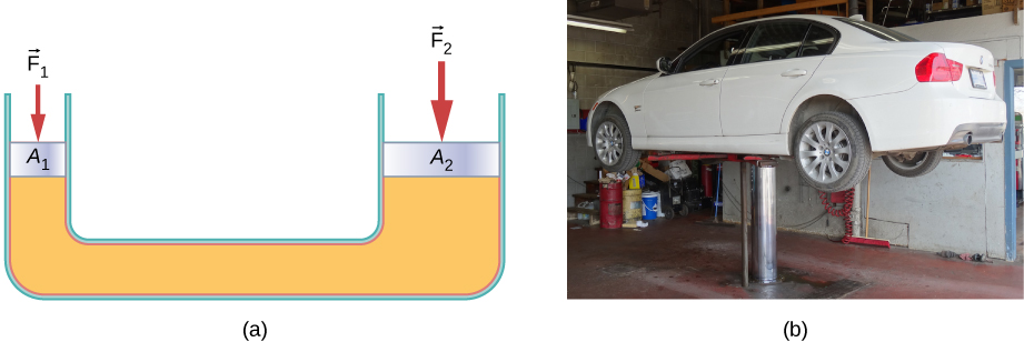
From Pascal’s principle, it can be shown that the force needed to lift the car is less than the weight of the car:

F 1 = A 1 A 2 F 2 ,

where F 1 is the force applied to lift the car, A 1 is the cross-sectional area of the smaller piston, A 2 is the cross sectional area of the larger piston, and F 2 is the weight of the car.

Calculating force on wheel cylinders: pascal puts on the brakes

Consider the automobile hydraulic system shown in [link] . Suppose a force of 100 N is applied to the brake pedal, which acts on the pedal cylinder (acting as a “master” cylinder) through a lever. A force of 500 N is exerted on the pedal cylinder. Pressure created in the pedal cylinder is transmitted to the four wheel cylinders. The pedal cylinder has a diameter of 0.500 cm and each wheel cylinder has a diameter of 2.50 cm. Calculate the magnitude of the force F 2 created at each of the wheel cylinders.

Practice Key Terms 3

Get Jobilize Job Search Mobile App in your pocket Now!

Get it on Google Play Download on the App Store Now


Source:  OpenStax, University physics volume 1. OpenStax CNX. Sep 19, 2016 Download for free at http://cnx.org/content/col12031/1.5
Google Play and the Google Play logo are trademarks of Google Inc.

Notification Switch

Would you like to follow the 'University physics volume 1' conversation and receive update notifications?

Ask