<< Chapter < Page Chapter >> Page >
Figure is a schematic drawing of a 5.0-m-long ladder resting against a wall. Ladder forms a 53 degree angle with the floor.
A 5.0-m-long ladder rests against a frictionless wall.

Strategy

We can identify four forces acting on the ladder. The first force is the normal reaction force N from the floor in the upward vertical direction. The second force is the static friction force f = μ s N directed horizontally along the floor toward the wall—this force prevents the ladder from slipping. These two forces act on the ladder at its contact point with the floor. The third force is the weight w of the ladder, attached at its CM located midway between its ends. The fourth force is the normal reaction force F from the wall in the horizontal direction away from the wall, attached at the contact point with the wall. There are no other forces because the wall is slippery, which means there is no friction between the wall and the ladder. Based on this analysis, we adopt the frame of reference with the y -axis in the vertical direction (parallel to the wall) and the x -axis in the horizontal direction (parallel to the floor). In this frame, each force has either a horizontal component or a vertical component but not both, which simplifies the solution. We select the pivot at the contact point with the floor. In the free-body diagram for the ladder, we indicate the pivot, all four forces and their lever arms, and the angles between lever arms and the forces, as shown in [link] . With our choice of the pivot location, there is no torque either from the normal reaction force N or from the static friction f because they both act at the pivot.

Figure is a free-body diagram for a ladder that forms an angle beta with the floor and rests against a wall. Force N is applied at the point at the floor and is perpendicular to the floor. Force W is applied at the mid-point of the ladder. Force F is applied at the point resting at the wall and is perpendicular to the wall. Force W forms an angle theta w with the direction of the lever arm. Theta w is equal to the sum of Pi and half Pi with the beta subtracted. Force F forms an angle theta F with the direction of the lever arm. Theta F is equal to the Pi minus beta.
Free-body diagram for a ladder resting against a frictionless wall.

Solution

From the free-body diagram, the net force in the x -direction is

+ f F = 0

the net force in the y -direction is

+ N w = 0

and the net torque along the rotation axis at the pivot point is
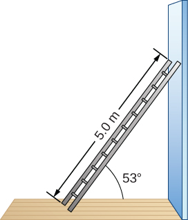
τ w + τ F = 0 .

where τ w is the torque of the weight w and τ F is the torque of the reaction F . From the free-body diagram, we identify that the lever arm of the reaction at the wall is r F = L = 5.0 m and the lever arm of the weight is r w = L / 2 = 2.5 m . With the help of the free-body diagram, we identify the angles to be used in [link] for torques: θ F = 180 ° β for the torque from the reaction force with the wall, and θ w = 180 ° + ( 90 ° β ) for the torque due to the weight. Now we are ready to use [link] to compute torques:

τ w = r w w sin θ w = r w w sin ( 180 ° + 90 ° β ) = L 2 w sin ( 90 ° β ) = L 2 w cos β τ F = r F F sin θ F = r F F sin ( 180 ° β ) = L F sin β .

We substitute the torques into [link] and solve for F :

L 2 w cos β + L F sin β = 0 F = w 2 cot β = 400.0 N 2 cot 53 ° = 150.7 N

We obtain the normal reaction force with the floor by solving [link] : N = w = 400.0 N . The magnitude of friction is obtained by solving [link] : f = F = 150.7 N . The coefficient of static friction is μ s = f / N = 150.7 / 400.0 = 0.377 .

The net force on the ladder at the contact point with the floor is the vector sum of the normal reaction from the floor and the static friction forces:

F floor = f + N = (150.7 N) ( i ^ ) + ( 400.0 N) ( + j ^ ) = ( −150.7 i ^ + 400.0 j ^ ) N.

Its magnitude is

F floor = f 2 + N 2 = 150.7 2 + 400.0 2 N = 427.4 N

and its direction is

φ = tan −1 ( N / f ) = tan −1 ( 400.0 / 150.7 ) = 69.3 ° above the floor.

We should emphasize here two general observations of practical use. First, notice that when we choose a pivot point, there is no expectation that the system will actually pivot around the chosen point. The ladder in this example is not rotating at all but firmly stands on the floor; nonetheless, its contact point with the floor is a good choice for the pivot. Second, notice when we use [link] for the computation of individual torques, we do not need to resolve the forces into their normal and parallel components with respect to the direction of the lever arm, and we do not need to consider a sense of the torque. As long as the angle in [link] is correctly identified—with the help of a free-body diagram—as the angle measured counterclockwise from the direction of the lever arm to the direction of the force vector, [link] gives both the magnitude and the sense of the torque. This is because torque is the vector product of the lever-arm vector crossed with the force vector, and [link] expresses the rectangular component of this vector product along the axis of rotation.

Get Jobilize Job Search Mobile App in your pocket Now!

Get it on Google Play Download on the App Store Now


Source:  OpenStax, University physics volume 1. OpenStax CNX. Sep 19, 2016 Download for free at http://cnx.org/content/col12031/1.5
Google Play and the Google Play logo are trademarks of Google Inc.

Notification Switch

Would you like to follow the 'University physics volume 1' conversation and receive update notifications?

Ask