Make certain there is a clear circuit diagram on which you can label all known and unknown resistances, emfs, and currents. If a current is unknown, you must assign it a direction. This is necessary for determining the signs of potential changes. If you assign the direction incorrectly, the current will be found to have a negative value—no harm done.
Apply the junction rule to any junction in the circuit. Each time the junction rule is applied, you should get an equation with a current that does not appear in a previous application—if not, then the equation is redundant.
Apply the loop rule to as many loops as needed to solve for the unknowns in the problem. (There must be as many independent equations as unknowns.) To apply the loop rule, you must choose a direction to go around the loop. Then carefully and consistently determine the signs of the potential changes for each element using the four bulleted points discussed above in conjunction with
[link] .
Solve the simultaneous equations for the unknowns. This may involve many algebraic steps, requiring careful checking and rechecking.
Check to see whether the answers are reasonable and consistent. The numbers should be of the correct order of magnitude, neither exceedingly large nor vanishingly small. The signs should be reasonable—for example, no resistance should be negative. Check to see that the values obtained satisfy the various equations obtained from applying the rules. The currents should satisfy the junction rule, for example.
The material in this section is correct in theory. We should be able to verify it by making measurements of current and voltage. In fact, some of the devices used to make such measurements are straightforward applications of the principles covered so far and are explored in the next modules. As we shall see, a very basic, even profound, fact results—making a measurement alters the quantity being measured.
Can Kirchhoff’s rules be applied to simple series and parallel circuits or are they restricted for use in more complicated circuits that are not combinations of series and parallel?
Kirchhoff's rules can be applied to any circuit since they are applications to circuits of two conservation laws. Conservation laws are the most broadly applicable principles in physics. It is usually mathematically simpler to use the rules for series and parallel in simpler circuits so we emphasize Kirchhoff’s rules for use in more complicated situations. But the rules for series and parallel can be derived from Kirchhoff’s rules. Moreover, Kirchhoff’s rules can be expanded to devices other than resistors and emfs, such as capacitors, and are one of the basic analysis devices in circuit analysis.
Kirchhoff’s rules can be used to analyze any circuit, simple or complex.
Kirchhoff’s first rule—the junction rule: The sum of all currents entering a junction must equal the sum of all currents leaving the junction.
Kirchhoff’s second rule—the loop rule: The algebraic sum of changes in potential around any closed circuit path (loop) must be zero.
The two rules are based, respectively, on the laws of conservation of charge and energy.
When calculating potential and current using Kirchhoff’s rules, a set of conventions must be followed for determining the correct signs of various terms.
The simpler series and parallel rules are special cases of Kirchhoff’s rules.
Conceptual questions
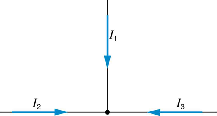
Can all of the currents going into the junction in
[link] be positive? Explain.
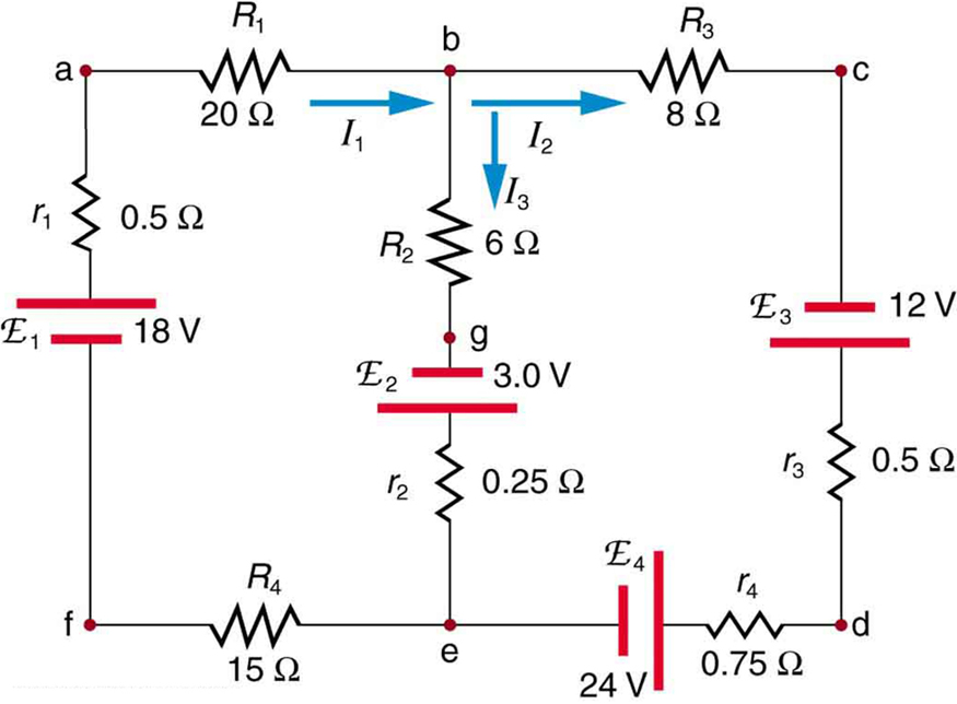
Apply the junction rule to junction b in
[link] . Is any new information gained by applying the junction rule at e? (In the figure, each emf is represented by script E.)
(a) What is the potential difference going from point a to point b in
[link] ? (b) What is the potential difference going from c to b? (c) From e to g? (d) From e to d?
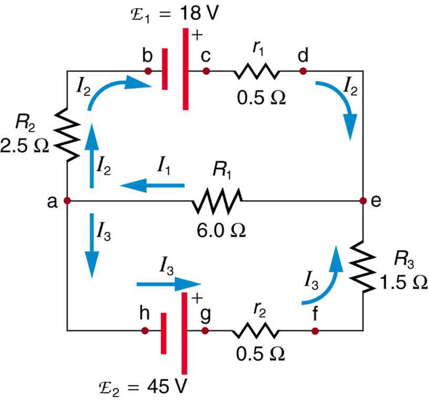
Consider the circuit in
[link] , and suppose that the emfs are unknown and the currents are given to be
,
, and
. (a) Could you find the emfs? (b) What is wrong with the assumptions?
(a) No, you would get inconsistent equations to solve.
(b)
. The assumed currents violate the junction rule.
A golfer on a fairway is 70 m away from the green, which sits below the level of the fairway by 20 m. If the golfer hits the ball at an angle of 40° with an initial speed of 20 m/s, how close to the green does she come?
A mouse of mass 200 g falls 100 m down a vertical mine shaft and lands at the bottom with a speed of 8.0 m/s. During its fall, how much work is done on the mouse by air resistance
Chemistry is a branch of science that deals with the study of matter,it composition,it structure and the changes it undergoes
Adjei
please, I'm a physics student and I need help in physics
Adjanou
chemistry could also be understood like the sexual attraction/repulsion of the male and female elements. the reaction varies depending on the energy differences of each given gender. + masculine -female.
Pedro
A ball is thrown straight up.it passes a 2.0m high window 7.50 m off the ground on it path up and takes 1.30 s to go past the window.what was the ball initial velocity
2. A sled plus passenger with total mass 50 kg is pulled 20 m across the snow (0.20) at constant velocity by a force directed 25° above the horizontal. Calculate (a) the work of the applied force, (b) the work of friction, and (c) the total work.
you have been hired as an espert witness in a court case involving an automobile accident. the accident involved car A of mass 1500kg which crashed into stationary car B of mass 1100kg. the driver of car A applied his brakes 15 m before he skidded and crashed into car B. after the collision, car A s
can someone explain to me, an ignorant high school student, why the trend of the graph doesn't follow the fact that the higher frequency a sound wave is, the more power it is, hence, making me think the phons output would follow this general trend?
Nevermind i just realied that the graph is the phons output for a person with normal hearing and not just the phons output of the sound waves power, I should read the entire thing next time
Joseph
Follow up question, does anyone know where I can find a graph that accuretly depicts the actual relative "power" output of sound over its frequency instead of just humans hearing
Joseph
"Generation of electrical energy from sound energy | IEEE Conference Publication | IEEE Xplore" ***ieeexplore.ieee.org/document/7150687?reload=true
A string is 3.00 m long with a mass of 5.00 g. The string is held taut with a tension of 500.00 N applied to the string. A pulse is sent down the string. How long does it take the pulse to travel the 3.00 m of the string?