

| << Chapter < Page | Chapter >> Page > |
Note that although the resistance in the circuit considered is negligible, the AC current is not extremely large because inductive reactance impedes its flow. With AC, there is no time for the current to become extremely large.
Consider the capacitor connected directly to an AC voltage source as shown in [link] . The resistance of a circuit like this can be made so small that it has a negligible effect compared with the capacitor, and so we can assume negligible resistance. Voltage across the capacitor and current are graphed as functions of time in the figure.
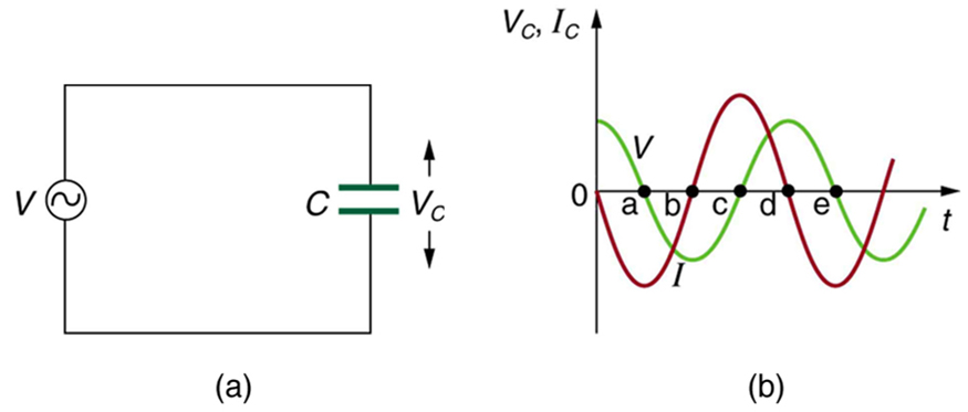
The graph in [link] starts with voltage across the capacitor at a maximum. The current is zero at this point, because the capacitor is fully charged and halts the flow. Then voltage drops and the current becomes negative as the capacitor discharges. At point a, the capacitor has fully discharged ( on it) and the voltage across it is zero. The current remains negative between points a and b, causing the voltage on the capacitor to reverse. This is complete at point b, where the current is zero and the voltage has its most negative value. The current becomes positive after point b, neutralizing the charge on the capacitor and bringing the voltage to zero at point c, which allows the current to reach its maximum. Between points c and d, the current drops to zero as the voltage rises to its peak, and the process starts to repeat. Throughout the cycle, the voltage follows what the current is doing by one-fourth of a cycle:
When a sinusoidal voltage is applied to a capacitor, the voltage follows the current by one-fourth of a cycle, or by a phase angle.
The capacitor is affecting the current, having the ability to stop it altogether when fully charged. Since an AC voltage is applied, there is an rms current, but it is limited by the capacitor. This is considered to be an effective resistance of the capacitor to AC, and so the rms current in the circuit containing only a capacitor is given by another version of Ohm’s law to be
where is the rms voltage and is defined (As with , this expression for results from an analysis of the circuit using Kirchhoff’s rules and calculus) to be
where is called the capacitive reactance , because the capacitor reacts to impede the current. has units of ohms (verification left as an exercise for the reader). is inversely proportional to the capacitance ; the larger the capacitor, the greater the charge it can store and the greater the current that can flow. It is also inversely proportional to the frequency ; the greater the frequency, the less time there is to fully charge the capacitor, and so it impedes current less.
(a) Calculate the capacitive reactance of a 5.00 mF capacitor when 60.0 Hz and 10.0 kHz AC voltages are applied. (b) What is the rms current if the applied rms voltage is 120 V?
Strategy
The capacitive reactance is found directly from the expression in . Once has been found at each frequency, Ohm’s law stated as can be used to find the current at each frequency.
Solution for (a)
Entering the frequency and capacitance into gives
Similarly, at 10 kHz,
Solution for (b)
The rms current is now found using the version of Ohm’s law in , given the applied rms voltage is 120 V. For the first frequency, this yields
Similarly, at 10 kHz,
Discussion
The capacitor reacts very differently at the two different frequencies, and in exactly the opposite way an inductor reacts. At the higher frequency, its reactance is small and the current is large. Capacitors favor change, whereas inductors oppose change. Capacitors impede low frequencies the most, since low frequency allows them time to become charged and stop the current. Capacitors can be used to filter out low frequencies. For example, a capacitor in series with a sound reproduction system rids it of the 60 Hz hum.
Notification Switch
Would you like to follow the 'College physics' conversation and receive update notifications?

|
|
|
|
|

|
|

|
|

|
|

|
|

|
|

|
|

|
|

|
|

|
|

|