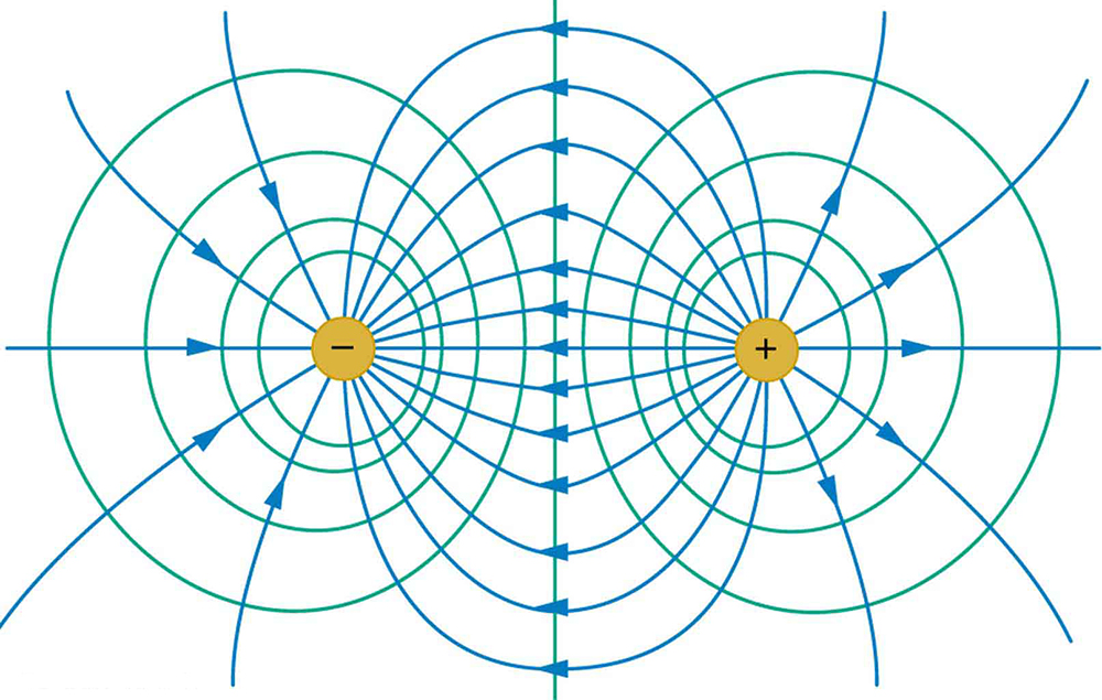
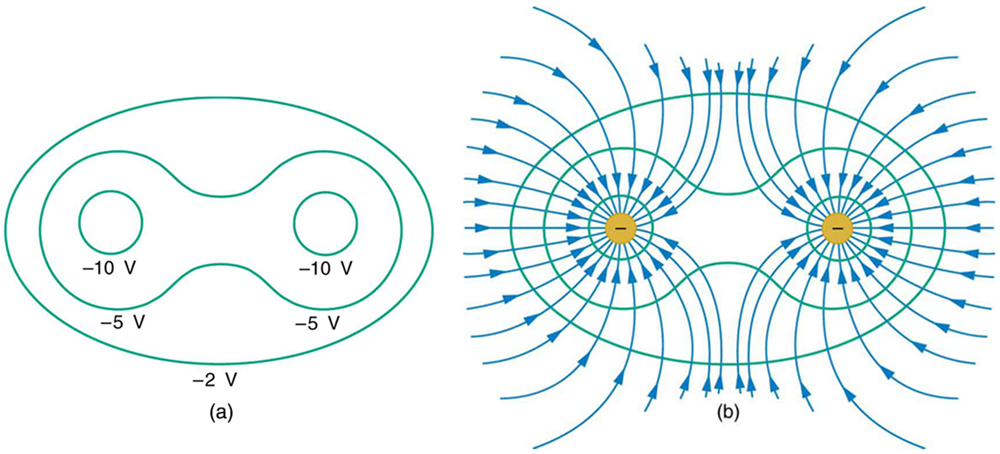
The electric field lines and equipotential lines for two equal but opposite charges. The equipotential lines can be drawn by making them perpendicular to the electric field lines, if those are known. Note that the potential is greatest (most positive) near the positive charge and least (most negative) near the negative charge.(a) These equipotential lines might be measured with a voltmeter in a laboratory experiment. (b) The corresponding electric field lines are found by drawing them perpendicular to the equipotentials. Note that these fields are consistent with two equal negative charges.
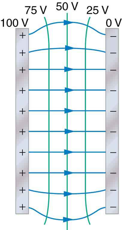
One of the most important cases is that of the familiar parallel conducting plates shown in
[link] . Between the plates, the equipotentials are evenly spaced and parallel. The same field could be maintained by placing conducting plates at the equipotential lines at the potentials shown.
The electric field and equipotential lines between two metal plates.
An important application of electric fields and equipotential lines involves the heart. The heart relies on electrical signals to maintain its rhythm. The movement of electrical signals causes the chambers of the heart to contract and relax. When a person has a heart attack, the movement of these electrical signals may be disturbed. An artificial pacemaker and a defibrillator can be used to initiate the rhythm of electrical signals. The equipotential lines around the heart, the thoracic region, and the axis of the heart are useful ways of monitoring the structure and functions of the heart. An electrocardiogram (ECG) measures the small electric signals being generated during the activity of the heart.
Section summary
An equipotential line is a line along which the electric potential is constant.
An equipotential surface is a three-dimensional version of equipotential lines.
Equipotential lines are always perpendicular to electric field lines.
The process by which a conductor can be fixed at zero volts by connecting it to the earth with a good conductor is called grounding.
Conceptual questions
What is an equipotential line? What is an equipotential surface?
Explain in your own words why equipotential lines and surfaces must be perpendicular to electric field lines.
Can different equipotential lines cross? Explain.
Problems&Exercises
(a) Sketch the equipotential lines near a point charge +
. Indicate the direction of increasing potential. (b) Do the same for a point charge
.
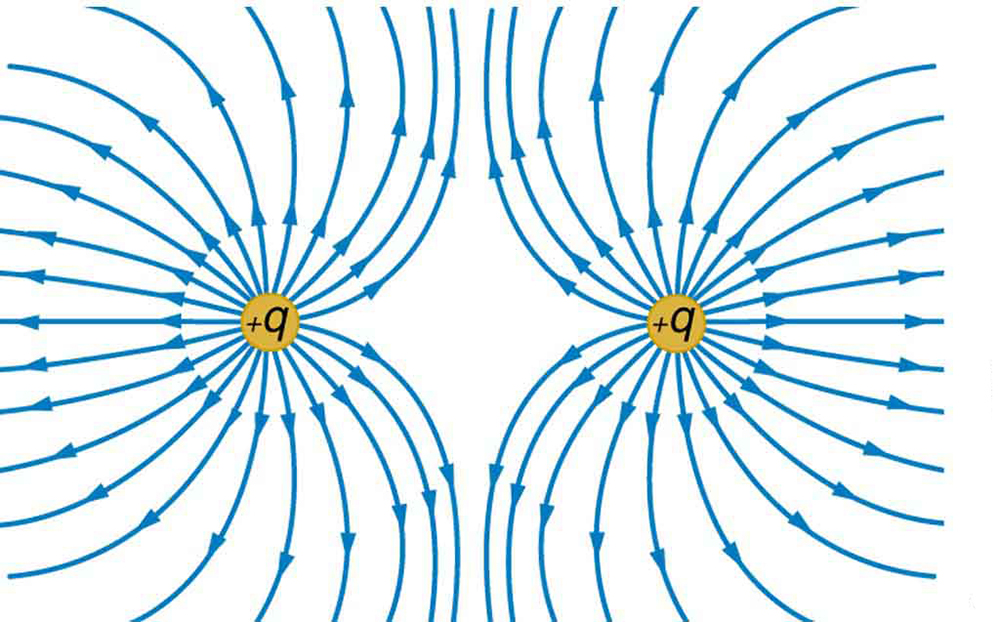
Sketch the equipotential lines for the two equal positive charges shown in
[link] . Indicate the direction of increasing potential.
The electric field near two equal positive charges is directed away from each of the charges.
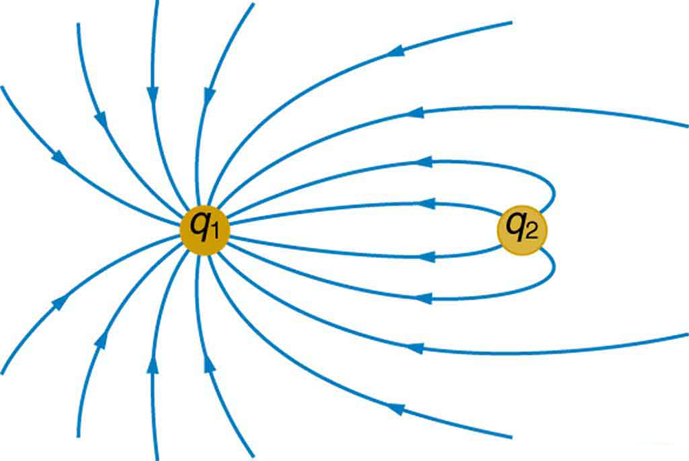
[link] shows the electric field lines near two charges
and
, the first having a magnitude four times that of the second. Sketch the equipotential lines for these two charges, and indicate the direction of increasing potential.
Sketch the equipotential lines a long distance from the charges shown in
[link] . Indicate the direction of increasing potential.
The electric field near two charges.
Sketch the equipotential lines in the vicinity of two opposite charges, where the negative charge is three times as great in magnitude as the positive. See
[link] for a similar situation. Indicate the direction of increasing potential.
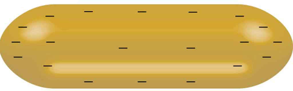
Sketch the equipotential lines in the vicinity of the negatively charged conductor in
[link] . How will these equipotentials look a long distance from the object?
A negatively charged conductor.
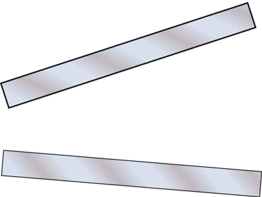
Sketch the equipotential lines surrounding the two conducting plates shown in
[link] , given the top plate is positive and the bottom plate has an equal amount of negative charge. Be certain to indicate the distribution of charge on the plates. Is the field strongest where the plates are closest? Why should it be?
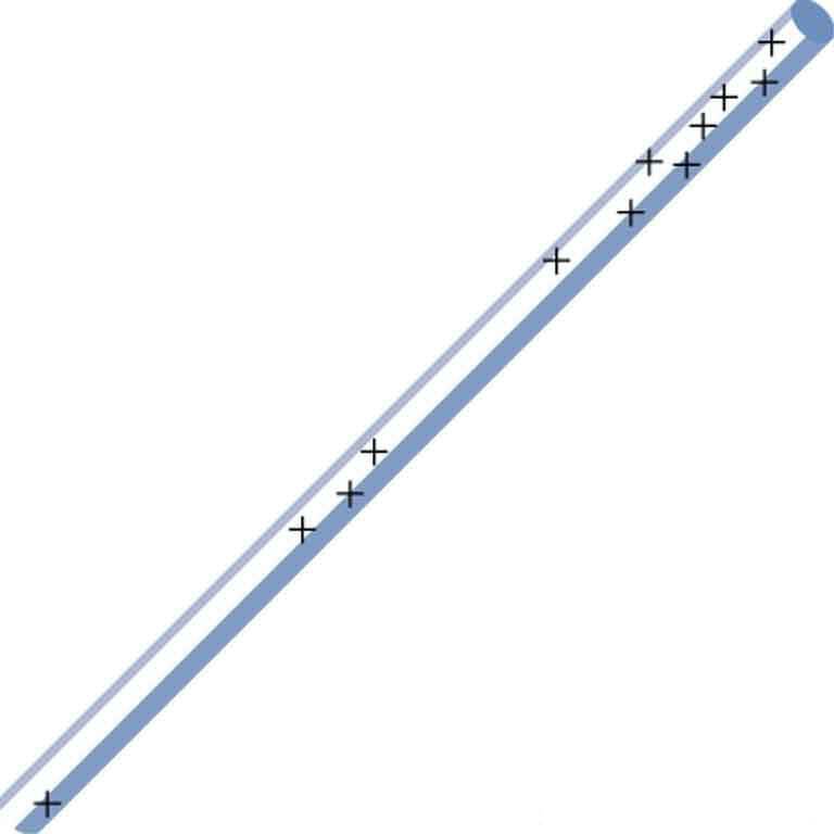
(a) Sketch the electric field lines in the vicinity of the charged insulator in
[link] . Note its non-uniform charge distribution. (b) Sketch equipotential lines surrounding the insulator. Indicate the direction of increasing potential.
A charged insulating rod such as might be used in a classroom demonstration.
The naturally occurring charge on the ground on a fine day out in the open country is
. (a) What is the electric field relative to ground at a height of 3.00 m? (b) Calculate the electric potential at this height. (c) Sketch electric field and equipotential lines for this scenario.
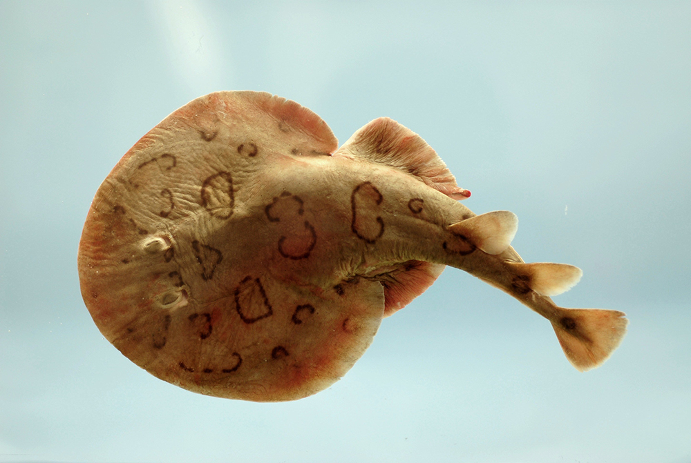
The lesser electric ray (
Narcine bancroftii )
maintains an incredible charge on its head and a charge equal in magnitude but opposite in sign on its tail (
[link] ). (a) Sketch the equipotential lines surrounding the ray. (b) Sketch the equipotentials when the ray is near a ship with a conducting surface. (c) How could this charge distribution be of use to the ray?
Lesser electric ray (
Narcine bancroftii ) (credit: National Oceanic and Atmospheric Administration, NOAA's Fisheries Collection).
the study of living organisms and their interactions with one another and their environment.
Wine
discuss the biological phenomenon and provide pieces of evidence to show that it was responsible for the formation of eukaryotic organelles in an essay form
advantage of electronic microscope is easily and clearly while disadvantage is dangerous because its electronic. advantage of light microscope is savely and naturally by sun while disadvantage is not easily,means its not sharp and not clear
Abdullahi
cell theory state that every organisms composed of one or more cell,cell is the basic unit of life
Abdullahi
is like gone fail us
DENG
cells is the basic structure and functions of all living things
A scanning electron microscope (SEM) is ideal for situations requiring high-resolution imaging of surfaces. It is commonly used in materials science, biology, and geology to examine the topography and composition of samples at a nanoscale level. SEM is particularly useful for studying fine details,