<< Chapter < Page Chapter >> Page >

Solution for (a)

Constructive interference occurs here when

2 t c = λ n 2 , n 2 , n 2 , . size 12{2t rSub { size 8{c} } = { {λ rSub { size 8{n} } } over {2} } ,` { {3λ rSub { size 8{n} } } over {2} } ,` { {5λ rSub { size 8{n} } } over {2} } ", "` dotslow } {}

The smallest constructive thickness t c size 12{t rSub { size 8{c} } } {} thus is

t c = λ n 4 = λ / n 4 = ( 650 nm ) / 1 . 333 4 = 122 nm. alignl { stack { size 12{t rSub { size 8{c} } = { {λ rSub { size 8{n} } } over {4} } = { {λ/n} over {4} } = { { { \( "650"`"nm" \) } slash {1 "." "333"} } over {4} } } {} #="122"`"nm" {} } } {}

The next thickness that gives constructive interference is t c = n / 4 , so that

t c = 366 nm. size 12{ { {t}} sup { ' } rSub { size 8{c} } ="366"`"nm"} {}

Finally, the third thickness producing constructive interference is t ′′ c n / 4 size 12{ { {t}} sup { '' } rSub { size 8{c} }<= 5λ rSub { size 8{n} } /4} {} , so that

t ′′ c = 610 nm. size 12{ { {t}} sup { '' } rSub { size 8{c} } ="610"`"nm"} {}

Solution for (b)

For destructive interference , the path length difference here is an integral multiple of the wavelength. The first occurs for zero thickness, since there is a phase change at the top surface. That is,

t d = 0. size 12{t rSub { size 8{d} } =0} {}

The first non-zero thickness producing destructive interference is

2 t d = λ n . size 12{2 { {t}} sup { ' } rSub { size 8{d} } =λ rSub { size 8{n} } } {}

Substituting known values gives

t d = λ n 2 = λ / n 2 = ( 650 nm ) / 1 . 333 2 = 244 nm. alignl { stack { size 12{ { {t}} sup { ' } rSub { size 8{d} } = { {λ"" lSub { size 8{n} } } over {2} } = { {λ/n} over {2} } = { { { \( "650"`"nm" \) } slash {1 "." "333"} } over {2} } } {} #="244"`"nm" {} } } {}

Finally, the third destructive thickness is 2 t ′′ d = n size 12{2 { {t}} sup { '' } rSub { size 8{d} } =2λ rSub { size 8{n} } } {} , so that

t ′′ d = λ n = λ n = 650 nm 1 . 333 = 488 nm. alignl { stack { size 12{ { {t}} sup { '' } rSub { size 8{d} } =λ rSub { size 8{n} } = { {λ} over {n} } = { {"650"`"nm"} over {1 "." "333"} } } {} #="488"`"nm" {} } } {}

Discussion

If the bubble was illuminated with pure red light, we would see bright and dark bands at very uniform increases in thickness. First would be a dark band at 0 thickness, then bright at 122 nm thickness, then dark at 244 nm, bright at 366 nm, dark at 488 nm, and bright at 610 nm. If the bubble varied smoothly in thickness, like a smooth wedge, then the bands would be evenly spaced.

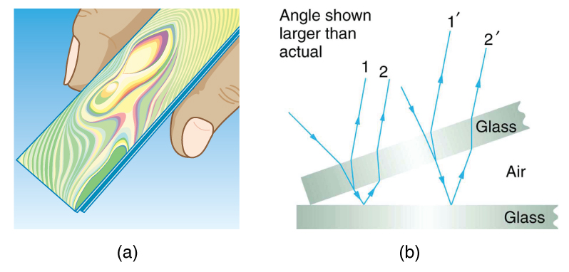
Another example of thin film interference can be seen when microscope slides are separated (see [link] ). The slides are very flat, so that the wedge of air between them increases in thickness very uniformly. A phase change occurs at the second surface but not the first, and so there is a dark band where the slides touch. The rainbow colors of constructive interference repeat, going from violet to red again and again as the distance between the slides increases. As the layer of air increases, the bands become more difficult to see, because slight changes in incident angle have greater effects on path length differences. If pure-wavelength light instead of white light is used, then bright and dark bands are obtained rather than repeating rainbow colors.

Figure A shows two microscope slides that have been pressed together. Multicolor swirling rainbow bands are visible coming from the slides. Figure B shows a cross section of two glass slides stacked one on top of the other. The lower slide is horizontal and the upper slide is tilted up at an angle that is larger than the actual angle between slides would be. Two rays come from above and impinge upon the slides. Their refraction and partial reflection is shown at each glass air interface.
(a) The rainbow color bands are produced by thin film interference in the air between the two glass slides. (b) Schematic of the paths taken by rays in the wedge of air between the slides.

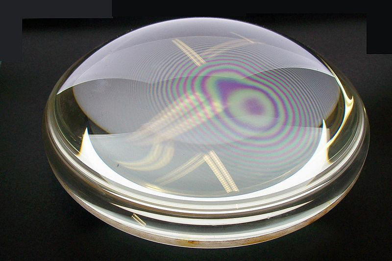
An important application of thin film interference is found in the manufacturing of optical instruments. A lens or mirror can be compared with a master as it is being ground, allowing it to be shaped to an accuracy of less than a wavelength over its entire surface. [link] illustrates the phenomenon called Newton’s rings, which occurs when the plane surfaces of two lenses are placed together. (The circular bands are called Newton’s rings because Isaac Newton described them and their use in detail. Newton did not discover them; Robert Hooke did, and Newton did not believe they were due to the wave character of light.) Each successive ring of a given color indicates an increase of only one wavelength in the distance between the lens and the blank, so that great precision can be obtained. Once the lens is perfect, there will be no rings.

This figure shows rainbow-colored concentric rings obtained when two plano-convex lenses are placed together with their flat surfaces in contact.
“Newton's rings” interference fringes are produced when two plano-convex lenses are placed together with their plane surfaces in contact. The rings are created by interference between the light reflected off the two surfaces as a result of a slight gap between them, indicating that these surfaces are not precisely plane but are slightly convex. (credit: Ulf Seifert, Wikimedia Commons)
Practice Key Terms 1

Get Jobilize Job Search Mobile App in your pocket Now!

Get it on Google Play Download on the App Store Now


Source:  OpenStax, College physics. OpenStax CNX. Jul 27, 2015 Download for free at http://legacy.cnx.org/content/col11406/1.9
Google Play and the Google Play logo are trademarks of Google Inc.

Notification Switch

Would you like to follow the 'College physics' conversation and receive update notifications?

Ask