

| << Chapter < Page | Chapter >> Page > |
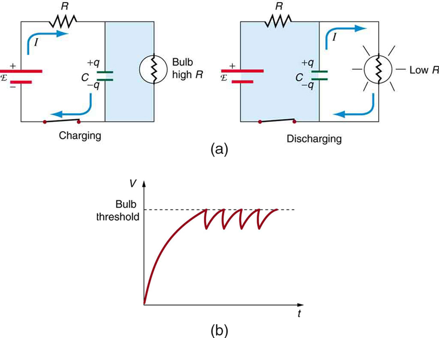
circuits are commonly used for timing purposes. A mundane example of this is found in the ubiquitous intermittent wiper systems of modern cars. The time between wipes is varied by adjusting the resistance in an circuit. Another example of an circuit is found in novelty jewelry, Halloween costumes, and various toys that have battery-powered flashing lights. (See [link] for a timing circuit.)
A more crucial use of circuits for timing purposes is in the artificial pacemaker, used to control heart rate. The heart rate is normally controlled by electrical signals generated by the sino-atrial (SA) node, which is on the wall of the right atrium chamber. This causes the muscles to contract and pump blood. Sometimes the heart rhythm is abnormal and the heartbeat is too high or too low.
The artificial pacemaker is inserted near the heart to provide electrical signals to the heart when needed with the appropriate time constant. Pacemakers have sensors that detect body motion and breathing to increase the heart rate during exercise to meet the body’s increased needs for blood and oxygen.
A heart defibrillator is used to resuscitate an accident victim by discharging a capacitor through the trunk of her body. A simplified version of the circuit is seen in [link] . (a) What is the time constant if an capacitor is used and the path resistance through her body is ? (b) If the initial voltage is 10.0 kV, how long does it take to decline to ?
Strategy
Since the resistance and capacitance are given, it is straightforward to multiply them to give the time constant asked for in part (a). To find the time for the voltage to decline to , we repeatedly multiply the initial voltage by 0.368 until a voltage less than or equal to is obtained. Each multiplication corresponds to a time of seconds.
Solution for (a)
The time constant is given by the equation . Entering the given values for resistance and capacitance (and remembering that units for a farad can be expressed as ) gives
Solution for (b)
In the first 8.00 ms, the voltage (10.0 kV) declines to 0.368 of its initial value. That is:
(Notice that we carry an extra digit for each intermediate calculation.) After another 8.00 ms, we multiply by 0.368 again, and the voltage is
Similarly, after another 8.00 ms, the voltage is
Discussion
So after only 24.0 ms, the voltage is down to 498 V, or 4.98% of its original value. Such brief times are useful in heart defibrillation, because the brief but intense current causes a brief but effective contraction of the heart. The actual circuit in a heart defibrillator is slightly more complex than the one in [link] , to compensate for magnetic and AC effects that will be covered in Magnetism .
Notification Switch
Would you like to follow the 'College physics' conversation and receive update notifications?

|
|
|
|
|

|
|

|
|

|
|

|
|

|
|

|
|
|
|
|

|
|

|
|

|