<< Chapter < Page Chapter >> Page >

Learning objectives

By the end of this section, you will be able to:

  • Calculate the impedance, phase angle, resonant frequency, power, power factor, voltage, and/or current in an RLC series circuit.
  • Draw the circuit diagram for an RLC series circuit.
  • Explain the significance of the resonant frequency.

Impedance

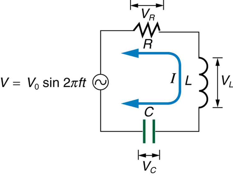
When alone in an AC circuit, inductors, capacitors, and resistors all impede current. How do they behave when all three occur together? Interestingly, their individual resistances in ohms do not simply add. Because inductors and capacitors behave in opposite ways, they partially to totally cancel each other’s effect. [link] shows an RLC series circuit with an AC voltage source, the behavior of which is the subject of this section. The crux of the analysis of an RLC circuit is the frequency dependence of X L size 12{X rSub { size 8{L} } } {} and X C size 12{X rSub { size 8{C} } } {} , and the effect they have on the phase of voltage versus current (established in the preceding section). These give rise to the frequency dependence of the circuit, with important “resonance” features that are the basis of many applications, such as radio tuners.

The figure describes an R LC series circuit. It shows a resistor R connected in series with an inductor L, connected to a capacitor C in series to an A C source V. The voltage of the A C source is given by V equals V zero sine two pi f t. The voltage across R is V R, across L is V L and across C is V C.
An RLC series circuit with an AC voltage source.

The combined effect of resistance R size 12{R} {} , inductive reactance X L size 12{X rSub { size 8{L} } } {} , and capacitive reactance X C size 12{X rSub { size 8{C} } } {} is defined to be impedance    , an AC analogue to resistance in a DC circuit. Current, voltage, and impedance in an RLC circuit are related by an AC version of Ohm’s law:

I 0 = V 0 Z or I rms = V rms Z . size 12{I rSub { size 8{0} } = { {V rSub { size 8{0} } } over {Z} } " or "I rSub { size 8{ ital "rms"} } = { {V rSub { size 8{ ital "rms"} } } over {Z} } "." } {}

Here I 0 size 12{I rSub { size 8{0} } } {} is the peak current, V 0 size 12{V rSub { size 8{0} } } {} the peak source voltage, and Z is the impedance of the circuit. The units of impedance are ohms, and its effect on the circuit is as you might expect: the greater the impedance, the smaller the current. To get an expression for Z size 12{Z} {} in terms of R , X L size 12{X rSub { size 8{L} } } {} , and X C size 12{X rSub { size 8{C} } } {} , we will now examine how the voltages across the various components are related to the source voltage. Those voltages are labeled V R size 12{V rSub { size 8{R} } } {} , V L size 12{V rSub { size 8{L} } } {} , and V C size 12{V rSub { size 8{C} } } {} in [link] .

Conservation of charge requires current to be the same in each part of the circuit at all times, so that we can say the currents in R size 12{R} {} , L size 12{L} {} , and C size 12{C} {} are equal and in phase. But we know from the preceding section that the voltage across the inductor V L size 12{V rSub { size 8{L} } } {} leads the current by one-fourth of a cycle, the voltage across the capacitor V C size 12{V rSub { size 8{C} } } {} follows the current by one-fourth of a cycle, and the voltage across the resistor V R size 12{V rSub { size 8{R} } } {} is exactly in phase with the current. [link] shows these relationships in one graph, as well as showing the total voltage around the circuit V = V R + V L + V C size 12{V=V rSub { size 8{R} } +V rSub { size 8{L} } +V rSub { size 8{C} } } {} , where all four voltages are the instantaneous values. According to Kirchhoff’s loop rule, the total voltage around the circuit V is also the voltage of the source.

You can see from [link] that while V R size 12{V rSub { size 8{R} } } {} is in phase with the current, V L size 12{V rSub { size 8{L} } } {} leads by 90º , and V C size 12{V rSub { size 8{C} } } {} follows by 90º . Thus V L size 12{V rSub { size 8{L} } } {} and V C size 12{V rSub { size 8{C} } } {} are 180º out of phase (crest to trough) and tend to cancel, although not completely unless they have the same magnitude. Since the peak voltages are not aligned (not in phase), the peak voltage V 0 size 12{V rSub { size 8{0} } } {} of the source does not equal the sum of the peak voltages across R size 12{R} {} , L size 12{L} {} , and C size 12{C} {} . The actual relationship is

V 0 = V 0 R 2 + ( V 0 L V 0 C ) 2 , size 12{V rSub { size 8{0} } = sqrt {V rSub { size 8{0R} } "" lSup { size 8{2} } + \( V rSub { size 8{0L} } - V rSub { size 8{0C} } \) rSup { size 8{2} } } ,} {}

where V 0 R size 12{V rSub { size 8{0R} } } {} , V 0 L size 12{V rSub { size 8{0L} } } {} , and V 0 C size 12{V rSub { size 8{0C} } } {} are the peak voltages across R size 12{R} {} , L size 12{L} {} , and C size 12{C} {} , respectively. Now, using Ohm’s law and definitions from Reactance, Inductive and Capacitive , we substitute V 0 = I 0 Z size 12{V rSub { size 8{0} } =I rSub { size 8{0} } Z} {} into the above, as well as V 0 R = I 0 R size 12{V rSub { size 8{0R} } =I rSub { size 8{0} } R} {} , V 0 L = I 0 X L size 12{V rSub { size 8{0L} } =I rSub { size 8{0} } X rSub { size 8{L} } } {} , and V 0 C = I 0 X C size 12{V rSub { size 8{0C} } =I rSub { size 8{0} } X rSub { size 8{C} } } {} , yielding

Questions & Answers

if three forces F1.f2 .f3 act at a point on a Cartesian plane in the daigram .....so if the question says write down the x and y components ..... I really don't understand
Syamthanda Reply
hey , can you please explain oxidation reaction & redox ?
Boitumelo Reply
hey , can you please explain oxidation reaction and redox ?
Boitumelo
for grade 12 or grade 11?
Sibulele
the value of V1 and V2
Tumelo Reply
advantages of electrons in a circuit
Rethabile Reply
we're do you find electromagnetism past papers
Ntombifuthi
what a normal force
Tholulwazi Reply
it is the force or component of the force that the surface exert on an object incontact with it and which acts perpendicular to the surface
Sihle
what is physics?
Petrus Reply
what is the half reaction of Potassium and chlorine
Anna Reply
how to calculate coefficient of static friction
Lisa Reply
how to calculate static friction
Lisa
How to calculate a current
Tumelo
how to calculate the magnitude of horizontal component of the applied force
Mogano
How to calculate force
Monambi
a structure of a thermocouple used to measure inner temperature
Anna Reply
a fixed gas of a mass is held at standard pressure temperature of 15 degrees Celsius .Calculate the temperature of the gas in Celsius if the pressure is changed to 2×10 to the power 4
Amahle Reply
How is energy being used in bonding?
Raymond Reply
what is acceleration
Syamthanda Reply
a rate of change in velocity of an object whith respect to time
Khuthadzo
how can we find the moment of torque of a circular object
Kidist
Acceleration is a rate of change in velocity.
Justice
t =r×f
Khuthadzo
how to calculate tension by substitution
Precious Reply
hi
Shongi
hi
Leago
use fnet method. how many obects are being calculated ?
Khuthadzo
khuthadzo hii
Hulisani
how to calculate acceleration and tension force
Lungile Reply
you use Fnet equals ma , newtoms second law formula
Masego
please help me with vectors in two dimensions
Mulaudzi Reply
how to calculate normal force
Mulaudzi
Got questions? Join the online conversation and get instant answers!
Jobilize.com Reply
Practice Key Terms 4

Get Jobilize Job Search Mobile App in your pocket Now!

Get it on Google Play Download on the App Store Now


Source:  OpenStax, College physics for ap® courses. OpenStax CNX. Nov 04, 2016 Download for free at https://legacy.cnx.org/content/col11844/1.14
Google Play and the Google Play logo are trademarks of Google Inc.

Notification Switch

Would you like to follow the 'College physics for ap® courses' conversation and receive update notifications?

Ask