<< Chapter < Page Chapter >> Page >

Learning objectives

By the end of this section, you will be able to:

  • Calculate the flux of a uniform magnetic field through a loop of arbitrary orientation.
  • Describe methods to produce an electromotive force (emf) with a magnetic field or a magnet and a loop of wire.

The information presented in this section supports the following AP® learning objectives and science practices:

  • 4.E.2.1 The student is able to construct an explanation of the function of a simple electromagnetic device in which an induced emf is produced by a changing magnetic flux through an area defined by a current loop (i.e., a simple microphone or generator) or of the effect on behavior of a device in which an induced emf is produced by a constant magnetic field through a changing area. (S.P. 6.4)

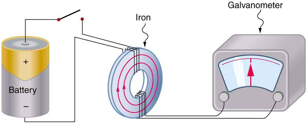
The apparatus used by Faraday to demonstrate that magnetic fields can create currents is illustrated in [link] . When the switch is closed, a magnetic field is produced in the coil on the top part of the iron ring and transmitted to the coil on the bottom part of the ring. The galvanometer is used to detect any current induced in the coil on the bottom. It was found that each time the switch is closed, the galvanometer detects a current in one direction in the coil on the bottom. (You can also observe this in a physics lab.) Each time the switch is opened, the galvanometer detects a current in the opposite direction. Interestingly, if the switch remains closed or open for any length of time, there is no current through the galvanometer. Closing and opening the switch induces the current. It is the change in magnetic field that creates the current. More basic than the current that flows is the emf that causes it. The current is a result of an emf induced by a changing magnetic field , whether or not there is a path for current to flow.

The picture shows Faraday’s apparatus for demonstrating that a magnetic field can produce a current. It consists of a cylinder shaped battery. The positive end of the battery is connected to an open switch. There is a ring shaped iron core consisting of a set of coils one on the top and another at the bottom. The other end of the switch is connected to one end of the top coil. The other end of the top coil is connected back to the battery. Both the ends of the bottom coil are shown connected across a galvanometer box which shows a null deflection.
Faraday’s apparatus for demonstrating that a magnetic field can produce a current. A change in the field produced by the top coil induces an emf and, hence, a current in the bottom coil. When the switch is opened and closed, the galvanometer registers currents in opposite directions. No current flows through the galvanometer when the switch remains closed or open.

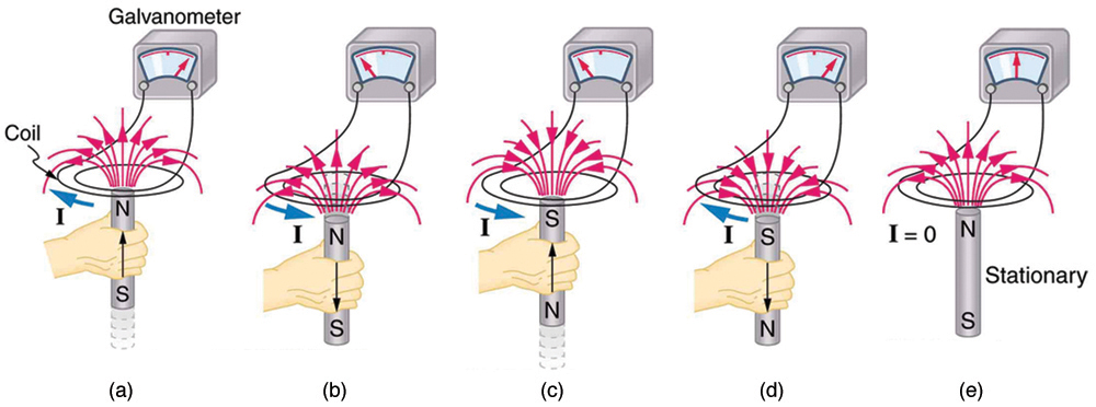
An experiment easily performed and often done in physics labs is illustrated in [link] . An emf is induced in the coil when a bar magnet is pushed in and out of it. Emfs of opposite signs are produced by motion in opposite directions, and the emfs are also reversed by reversing poles. The same results are produced if the coil is moved rather than the magnet—it is the relative motion that is important. The faster the motion, the greater the emf, and there is no emf when the magnet is stationary relative to the coil.

The diagram shows five stages of an experiment done by moving a magnet relative to a coil and measuring the e m f produced. The first stage of the experiment shows a wire coil with two loops connected across a galvanometer. The loop is in horizontal plane. A cylindrical rod shaped magnet is moved upward through the loop with the north pole of the magnet facing the loop and the South Pole away from the loop. The magnetic lines of force of the magnet are shown to emerge out from the North Pole and intersect the coil. A current is shown to be induced in the coil in clockwise direction. The galvanometer needle is shown to deflect toward right. The second stage of the experiment shows the next state of the first stage of the experiment. The cylindrical rod shaped magnet is now moved downward away from the loop with the north pole of the magnet facing the loop and South Pole away from the loop. The magnetic lines of force of the magnet are shown to emerge out from the North Pole and intersect the coil. A current is shown to be induced in the coil in anti clockwise direction. The galvanometer needle is shown to deflect toward left. The third stage of the experiment shows a wire coil with two loops connected across a galvanometer. The loop is in horizontal plane. A cylindrical rod shaped magnet is moved upward through the loop with the south pole of the magnet facing the loop and the North Pole away from the loop. The magnetic lines of force of the magnet are shown to merge into the South Pole and intersect the coil. A current is shown to be induced in the coil in anti clockwise direction. The galvanometer needle is shown to deflect toward left. The fourth stage of the experiment shows the next state of the third stage of the experiment. The cylindrical rod shaped magnet is now moved downward away from the loop with the south pole of the magnet facing the loop and the North Pole away from the loop. The magnetic lines of force of the magnet are shown to merge into the South Pole and intersect the coil. A current is shown to be induced in the coil in clockwise direction. The galvanometer needle is shown to deflect toward right. The fifth stage of the experiment shows a wire coil with two loops connected across a galvanometer. The loop is in horizontal plane. A cylindrical rod shaped magnet is held stationary near the loop with the north pole of the magnet facing the loop and south away from the loop. The magnetic lines of force of the magnet are shown to emerge out from the North Pole and intersect the coil. No current is induced in the coil. The galvanometer needle does not deflect.
Movement of a magnet relative to a coil produces emfs as shown. The same emfs are produced if the coil is moved relative to the magnet. The greater the speed, the greater the magnitude of the emf, and the emf is zero when there is no motion.

The method of inducing an emf used in most electric generators is shown in [link] . A coil is rotated in a magnetic field, producing an alternating current emf, which depends on rotation rate and other factors that will be explored in later sections. Note that the generator is remarkably similar in construction to a motor (another symmetry).

Questions & Answers

what is phylogeny
Odigie Reply
evolutionary history and relationship of an organism or group of organisms
AI-Robot
ok
Deng
what is biology
Hajah Reply
the study of living organisms and their interactions with one another and their environments
AI-Robot
what is biology
Victoria Reply
HOW CAN MAN ORGAN FUNCTION
Alfred Reply
the diagram of the digestive system
Assiatu Reply
allimentary cannel
Ogenrwot
How does twins formed
William Reply
They formed in two ways first when one sperm and one egg are splited by mitosis or two sperm and two eggs join together
Oluwatobi
what is genetics
Josephine Reply
Genetics is the study of heredity
Misack
how does twins formed?
Misack
What is manual
Hassan Reply
discuss biological phenomenon and provide pieces of evidence to show that it was responsible for the formation of eukaryotic organelles
Joseph Reply
what is biology
Yousuf Reply
the study of living organisms and their interactions with one another and their environment.
Wine
discuss the biological phenomenon and provide pieces of evidence to show that it was responsible for the formation of eukaryotic organelles in an essay form
Joseph Reply
what is the blood cells
Shaker Reply
list any five characteristics of the blood cells
Shaker
lack electricity and its more savely than electronic microscope because its naturally by using of light
Abdullahi Reply
advantage of electronic microscope is easily and clearly while disadvantage is dangerous because its electronic. advantage of light microscope is savely and naturally by sun while disadvantage is not easily,means its not sharp and not clear
Abdullahi
cell theory state that every organisms composed of one or more cell,cell is the basic unit of life
Abdullahi
is like gone fail us
DENG
cells is the basic structure and functions of all living things
Ramadan
What is classification
ISCONT Reply
is organisms that are similar into groups called tara
Yamosa
in what situation (s) would be the use of a scanning electron microscope be ideal and why?
Kenna Reply
A scanning electron microscope (SEM) is ideal for situations requiring high-resolution imaging of surfaces. It is commonly used in materials science, biology, and geology to examine the topography and composition of samples at a nanoscale level. SEM is particularly useful for studying fine details,
Hilary
Got questions? Join the online conversation and get instant answers!
Jobilize.com Reply
Practice Key Terms 2

Get Jobilize Job Search Mobile App in your pocket Now!

Get it on Google Play Download on the App Store Now


Source:  OpenStax, College physics for ap® courses. OpenStax CNX. Nov 04, 2016 Download for free at https://legacy.cnx.org/content/col11844/1.14
Google Play and the Google Play logo are trademarks of Google Inc.

Notification Switch

Would you like to follow the 'College physics for ap® courses' conversation and receive update notifications?

Ask