

| << Chapter < Page | Chapter >> Page > |
where
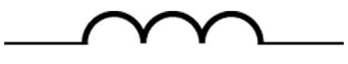
is the self-inductance of the device. A device that exhibits significant self-inductance is called an
inductor , and given the symbol in
[link] .
A 1 H inductor is a large inductor. To illustrate this, consider a device with that has a 10 A current flowing through it. What happens if we try to shut off the current rapidly, perhaps in only 1.0 ms? An emf, given by , will oppose the change. Thus an emf will be induced given by . The positive sign means this large voltage is in the same direction as the current, opposing its decrease. Such large emfs can cause arcs, damaging switching equipment, and so it may be necessary to change current more slowly.
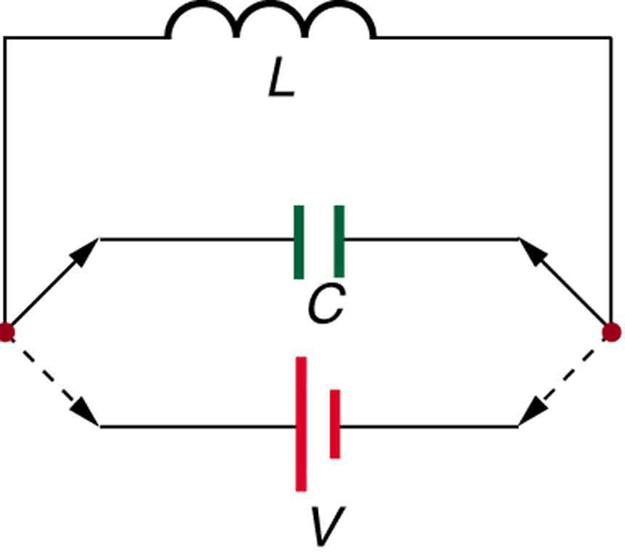
There are uses for such a large induced voltage. Camera flashes use a battery, two inductors that function as a transformer, and a switching system or oscillator to induce large voltages. (Remember that we need a changing magnetic field, brought about by a changing current, to induce a voltage in another coil.) The oscillator system will do this many times as the battery voltage is boosted to over one thousand volts. (You may hear the high pitched whine from the transformer as the capacitor is being charged.) A capacitor stores the high voltage for later use in powering the flash. (See [link] .)
It is possible to calculate for an inductor given its geometry (size and shape) and knowing the magnetic field that it produces. This is difficult in most cases, because of the complexity of the field created. So in this text the inductance is usually a given quantity. One exception is the solenoid, because it has a very uniform field inside, a nearly zero field outside, and a simple shape. It is instructive to derive an equation for its inductance. We start by noting that the induced emf is given by Faraday’s law of induction as and, by the definition of self-inductance, as . Equating these yields
Solving for gives
This equation for the self-inductance of a device is always valid. It means that self-inductance depends on how effective the current is in creating flux; the more effective, the greater / is.
Let us use this last equation to find an expression for the inductance of a solenoid. Since the area of a solenoid is fixed, the change in flux is . To find , we note that the magnetic field of a solenoid is given by . (Here , where is the number of coils and is the solenoid’s length.) Only the current changes, so that . Substituting into gives
Notification Switch
Would you like to follow the 'College physics' conversation and receive update notifications?

|
|
|
|
|

|
|

|
|

|
|

|
|

|
|

|
|

|
|

|
|

|
|

|