- The objective of this chapter is to discuss various techniques for the control of electric machines. Basic techniques for speed and torque control will be illustrated with typical configurations of drive electronics that are used to implement the control algorithms.
- The discussion of this chapter is limited to steady-state operation. The steady-state picture presented here is quite adequate for a wide variety of electricmachine applications.- In the discussion of torque control for synchronous and induction machines, the techniques of field-oriented or vector control are introduced and the analogy is made with torque control in dc motors. This material is somewhat more sophisticated mathematically than the speed-control discussion and requires application of the dq0 transformations.
Control of dc motors
Speed control
The three most common speed-control methods for dc motors are adjustment of the flux, usually by means of field-current control, adjustment of the resistance associated with the armature circuit, and adjustment of the armature terminal voltage.
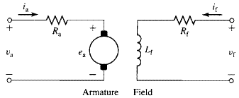
Field-Current Control: In part because it involves control at a relatively low power level, field-current control is frequently used to control the speed of a dc motor with separately excited or shunt field windings. The equivalent circuit for a separately excited dc machine is in Fig. 10.1. The shunt field current can be adjusted by means of a variable resistance in series with the shunt field. Alternatively, the field current can be supplied by power-electronic circuits which can be used to rapidly change the field current in response to a wide variety of control signals.
Figure 10.2a shows a switching scheme for pulse-width modulation of the field voltage. It consists of a rectifier which rectifies the ac input voltage, a dc-link capacitor which filters the rectified voltage, producing a dc voltage
, and a pulse-width modulator.
In this system, because only a unidirectional field current is required, the pulsewidth modulator consists of a single switch and a free-wheeling diode. Assuming both the switch and diode to be ideal, the average voltage across the field winding will be equal to
(10.1)
where D is the duty cycle of the switching waveform; i.e., D is the fraction of time that the switch S is on. Figure 10.2b shows the resultant field current.
In the steady-state the average voltage across the inductor must equal zero, the average field current
will thus be equal to
(10.2)
Figure 10.1 Equivalent circuit for a separately excited dc motor.
Figure 10.2 (a) Pulse-width modulation system for a dc-machine field winding.
(b) Field-current waveform.
Thus, the field current can be controlled simply by controlling the duty cycle of the pulse-width modulator. If the field-winding time constant
is long compared to the switching time, the ripple current
will be small compared to the average current
.
To examine the effect of field-current control, let us begin with the case of a dc motor driving a load of constant torque
. The generated voltage: