

| << Chapter < Page | Chapter >> Page > |
Phasors may be used to analyze the behavior of electrical and mechanical systems that have reached a kind of equilibrium called sinusoidal steady state . In the sinusoidal steady state, every voltage and current (or force and velocity) in a system is sinusoidal with angular frequency . However, the amplitudes and phases of these sinusoidal voltages and currents are all different. For example, the voltage across a resistor might lead the voltage across a capacitor by ( radians) and lag the voltage across an inductor by .
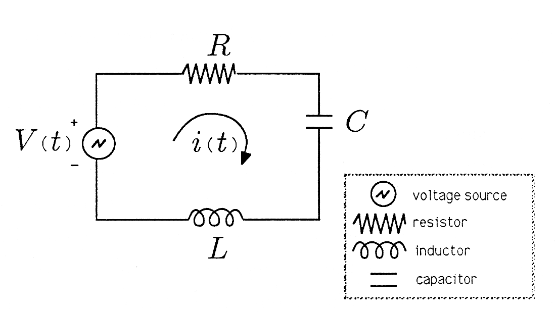
In order to make our application of phasors to electrical systems concrete, we consider the series RLC circuit illustrated in [link] . The arrow labeled denotes a current that flows in response to the voltage applied,and the + and - on the voltage source indicate that the polarity of the applied voltage is positive on the top and negative on the bottom. Our convention is that current flows from positive to negative, in this case clockwise in the circuit.
We will assume that the voltage source is an audio oscillator that pro- duces the voltage
We represent this voltage as the complex signal
and give it the phasor representation
We then describe the voltage source by the phasor V and remember that we can always compute the actual voltage by multiplying by and taking the real part:
Circuit Laws. In your circuits classes you will study the Kirchhoff laws that govern the low frequency behavior of circuits built from resistors , inductors , and capacitors . In your study you will learn that the voltage dropped across a resistor is related to the current that flows through it by the equation
You will learn that the voltage dropped across an inductor is proportional to the derivative of the current that flows through it, and the voltage droppedacross a capacitor is proportional to the integral of the current that flows through it:
Phasors and Complex Impedance. Now suppose that the current in the preceding equations is sinusoidal, of the form
We may rewrite as
where is the phasor representation of .
The voltage dropped across the resistor is
Thus the phasor representation for is
We call R the impedance of the resistor because R is the scale constant that relates the “phasor voltage V R ' to the “phasor current I .”
The voltage dropped across the inductor is
The derivative may be moved through the operator (see [link] ) to produce the result
Thus the phasor representation of
We call the impedance of the inductor because is the complex scale constant that relates “phasor voltage ' to “phasor current .”
Notification Switch
Would you like to follow the 'A first course in electrical and computer engineering' conversation and receive update notifications?

|
|

|
|

|
|

|
|

|
|

|
|

|
|
|
|
|
|
|
|

|