shows the data flow for the real time implementation of the image processing algorithms. The algorithms will be implemented using the DSK6416. A MATLAB will run simultaneously in the PC. This script will read the source picture from a file in the PC, convert it to grayscale and send it to the DSK6416 through an RTDX channel. The processed picture will be sent from the DSK6416 through a second RTDX channel. The script will display three images:
The original color picture
The grayscale picture
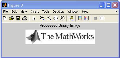
The processed image
Real Time Implementation Environment
Ccs code generation
Use the model created in chapter 2.
Add the "From RTDX" from the "RTDX Instrumentation" group of the "Embedded Target for the TI TMS320C6000 DSP" Blockset (Please refer to Figure 15). This block will be used receive data from the PC using a specified RTDX.
The "From RTDX" Block
Configure the block to receive data from a channel named "inputimage" as shown in Figure 16
If you are using the XDS560 or the Blackhawk USB560, you will need to enable High Speed RTDX in the "C61416DSK" block. . For the test we will send in an image over RTDX
The "Output Dimensions" should contain the Frame size . The selection of ‘Blocking Mode’ will cause the code running on the DSP to wait until the RTDX transfer is complete before executing. This will give the MATLAB script full control over the execution.
Configuring the Input Channel
Add the "To RTDX" from the "RTDX Instrumentation" group of the "Embedded Target for the TI TMS320C6000 DSP" Blockset (Please refer to Figure 15). This block will be used to send the processed image to the PC using a specified RTDX.
The "To RTDX" Block Configure the block to send data through a channel named "outputimage" as shown in Figure 9.
Configuring the Output Channel
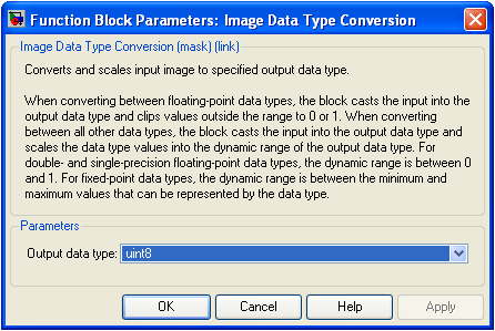
The RTDX channel transfers data in the uint8 format. Therefore the output of the Edge Detection Block should be converted to this format. Add the "Convert Image" block from from the "Conversions" group of the Video and Image Processing Blockset, (Please refer to Figure 19). The block should be configured as shown in Figure 20.
The Image Conversion BlockThe Image Conversion Configuration
Save your model (We used the name “stills_R_W.mdl”). Your model should look as shown in Figure 21.
Reading and Displaying a Picture
Now you can generate the code to your DSK by using Ctrl-B
If you do so, the build will fail at compilation in CCS due to an ISRAM space issue. In this case, we can fix this by redefining the location for .far as SDRAM rather than ISRAM (the default) in the board properties box. Rebuild, and it should compile fine. . When the model builds, it creates an object in the MATLAB workspace which represents CCS, by default called CCS_Obj. This object will be used to interact with the application on the DSP from MATLAB.
Build the project. Double-click the “Build Project” block.
Load the project. Double-click the “Load Project” block.
Run the target. Double-click the “Run” block. It should now be running, as displayed in CCS:
CCS Compilation Display
The matlab script
The purpose of the MATLAB code we want is to define an interface with the RTDX channels, to control the execution of the application on the processor, to send/retrieve data from the processor and to display it. An example script, “picture_script.m” will do this. The steps are also detailed below:
With the application running, we can configure the RTDX channels in CCS.
%% Configure RTDX channels% Identify RTDX channel names/modes
 chan_struct(1).name = 'inputimage';chan_struct(1).mode = 'w';
 chan_struct(2).name = 'outputimage';chan_struct(2).mode = 'r';
 % Identify RTDX host buffer parametersRTDX_config_struct.Buffsize = 32768;
 RTDX_config_struct.Nbuffers = 4;RTDX_config_struct.Mode = 'continuous';
 % Set up RTDXr = setupRTDX(CCS_Obj, chan_struct, RTDX_config_struct);
This This sets up a writeable RTDX channel to inputimage and a readable RTDX channel to outputimage. The names used are those in the blocks in the Simulink model.
Once running, we enable the RTDX channels for use, and get some data to send to the DSP – in this case a grayscale image taken from a file.
%% Enable RTDX
r.enable('all');%% Import an image from file to send to the DSP
Y = imread('TMW2.jpg');I = rgb2gray(Y);
We then send this to the DSP:
%% Send test frame to target via RTDX
r.writemsg('inputimage', I);
On receipt of this message, the DSP will process the data and send it back over the return RTDX channel, and then wait for further input.
We can read the processed data back:
%% Read processed test frame from DSP
O = r.readmsg('outputimage', 'uint8', size(I));
Receive real-time job alerts and never miss the right job again
Source:
OpenStax, From matlab and simulink to real-time with ti dsp's. OpenStax CNX. Jun 08, 2009 Download for free at http://cnx.org/content/col10713/1.1
Google Play and the Google Play logo are trademarks of Google Inc.
Notification Switch
Would you like to follow the 'From matlab and simulink to real-time with ti dsp's' conversation and receive update notifications?