

| << Chapter < Page | Chapter >> Page > |
The cell can be modeled as a leaky capacitor that separates charge by controlling the flow of ions across the cell membrane, making a difference between potentials and across the membrane ( ). This model approximates the subthreshold voltage ( before it reaches the threshold voltage ) and the time that does reach threshold . When reaches the threshold voltage, experiences a sharp increase then decrease and the cell is said to have “spiked" or “fired".
Let denote the membrane capacitance, and denote the conductances of the chloride channels and the synapse, respectively, and denote the reversal potential (the voltage at which no net flow of chloride ions occurs). is determined by the equilibrium concentrations of the ion of the associated channel, [link] . Input from other cells adds excitatory synaptic current. This input allows for the cell to depolarize and eventually reach and fire, which sends an electric signal to neighboring cells. The electric signal from a neighboring cell allows for voltage-gated channels to open, which affects the synaptic conductance . We set the reversal potential above a threshold voltage so that as increases and the channels open, the cell's voltage approaches the threshold . When , the cell fires [link] . See [link] for a model of a cell as a circuit [link] . The synaptic conductance is governed by the ODE
where is the decay constant, is the weight of synaptic input from the th synapse, is the set of input spike times for the presynaptic cell , and is the Dirac delta function. From Dr. Cox's book [link] , we see that applying Kirchoff's current law results in
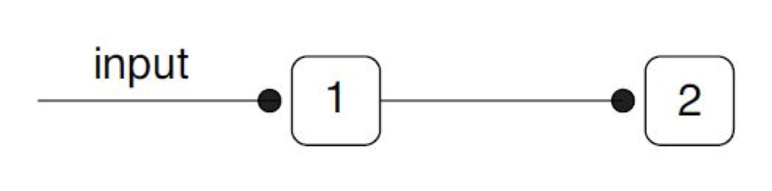

We use the IAF model for single cells, and we connect these cells into a ring of 120 place cells to simulate the DRE [link] . The 120-cell ring is depicted in [link] . Each cell receives external spatial input as well as input from neighboring cells. The conductances and voltages of Cells 1 and 2 are depicted in [link] as calculated by equations [link] and [link] . We monitor the weights of the connections between neighboring cells over time, where there is an arbitrary maximum weight bound so that the weights do not approach infinity and a minimum weight bound of 0 so the weights do not become negative. We also monitor how the changes of the weights affect the position of the place fields. See [link] for a depiction of the IAF model.
Notification Switch
Would you like to follow the 'The art of the pfug' conversation and receive update notifications?

|
|

|
|

|
|

|
|

|
|

|
|

|
|
|
|

|
|

|