

| << Chapter < Page | Chapter >> Page > |
For a detailed description of ion implant model selection, see Chapter 3: “SSUPREM4 Models”, Section 3.5:“Ion Implantation Models”.
You can specify tilt and rotation angles of the ion beam. Positive tilt angles correspond to the ion beam coming from the top left. Specifying the rotation angle makes sense only for non-zero tilt angles. Zero rotation means that the ion beam vector lies in the plane parallel to the 2D simulation plane. 90° rotation means that the ion beam vector lies in the plane perpendicular to the simulation plane.
Selecting Continual rotation causes SSUPREM4 to rotate the wafer, i.e., implantation will be performed at 24 different rotation angles from 0 to 345°, in increments of 15°.
There are several damage models available in SSUPREM4. These models allow you to estimate distributions of various defects generated after ion implantation. For more details about the damage models and their effect on subsequent diffusion, see Chapter 3: “SSUPREM4 Models”, Section
7.7.6:“Ion Implantation Damage”.
When the Monte Carlo model is selected, you can specify several additional optional parameters (See Figure 7.36). The first three parameters are related to the Damage model (Point defects, {311}-clusters, and dislocation loops). The three others control Monte Carlo calculation (initial random number, number of trajectories, and smoothing). See Table 7.6 for a quick reference of ATHENA implant models.
Table 7.6. ATHENA Implant Model Reference
| Process | Model | Assumption | Recommendation |
| Implant | SIMS Verified DualPearson (SVDP) - Default | Empirical | See Chapter 3: “SSUPREM4 Models”, Table 3-7. |
| Single Pearson | Analytic | All other cases | |
| Monte CarloMonte or BCA | Statistical | Multi-layer structures: angled implants into a structure where many ions could be reflected (trenches); when channeling is not described by SVDP; high or very low energy | |
| SiliconType | Amorphous | No channeling effect is included | Most of implant profile is within amorphous materials (oxide, polysilicon, pre- amorphized silicon); channeling is negligible or not important |
| Crystal - Default | Channeling effect is included | When channeling effects are important: light ions (boron, phosphorus)_, zero or close to 0° tilt, implant through thin amorphous layer into crystalline substrate |

Figure 7.36. ATHENA Implant Window continued on next page

Figure 7.36. ATHENA Implant Window
7.7.7 Simulating Diffusion
Simulation of thermal process steps is a focal point of SSUPREM4. The hierarchy of diffusion and oxidation models is described in this chapter and in Chapter 3: “SSUPREM4 Models”, Sections 3.1: “Diffusion Models” and 3.3: “Oxidation Models”. This section will demonstrate how to set different parameters and models of diffusion, oxidation and silicidation. The last process will take place only if at least one refractory metal or silicide layer is present in the structure.
The parameters and models of a diffusion/oxidation step can be prepared from the ATHENA Diffuse Menu. (Figure 7.37).
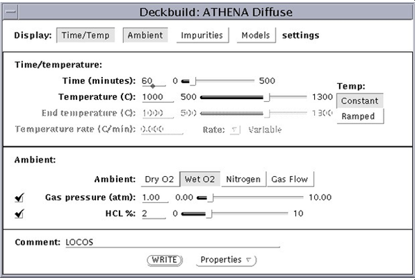
Figure 7.37. ATHENA Diffuse Menu.
To open this menu, select Process→Diffuse... in the Deckbuild Commands menu. The Diffuse menu has four sections. Only the Time/Temperature and Ambient fields appear initially. The Impurities and Models fields appear only when the corresponding check boxes are selected.
Notification Switch
Would you like to follow the 'Solid state physics and devices-the harbinger of third wave of civilization' conversation and receive update notifications?

|
|

|
|

|
|
|
|

|
|

|
|

|
|
|
|
|

|
|
|
|