

| << Chapter < Page | Chapter >> Page > |
4.1. Physical Significance of hybrid parameters (h-parameters) of BJT.
In small signal analysis of solid state circuits, we use h-model for BJT either connected as Common Base or Common Emitter configuration. We treat BJT as a Black Box and we look at open circuit or short circuit parameters at the input and output port as shown in Figure 4.1.1.
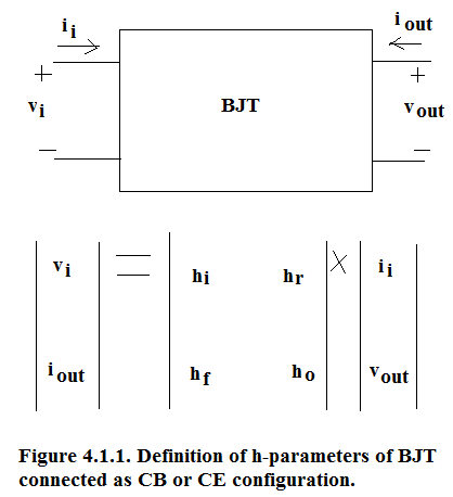
Definition of h-parameters:

Here incremental output voltage is kept at zero to measure input impedance h i of BJT circuit configuration. Incremental Output Voltage being kept at zero means that output DC Voltage(V CB in case of CB circuit configuration and V CE in case of CE configuration) is kept constant.

Here incremental input current is kept at zero to measure reverse transmission factor h r of BJT circuit configuration. Incremental Input Current being kept at zero means that input DC Current(I E in case of CB circuit configuration and I B in case of CE configuration) is kept constant.

Here incremental output voltage is kept at zero to measure forward short circuit current gain h f of BJT circuit configuration. Incremental Output Voltage being kept at zero means that output DC Voltage (V CB in case of CB circuit configuration and V CE in case of CE configuration) is kept constant.

Here incremental input current is kept at zero to measure output admittance h o of BJT circuit configuration. Incremental Input Current being kept at zero means that input DC Current(I E in case of CB circuit configuration and I B in case of CE configuration) is kept constant.
For CB Circuit configuration, subscript b is added and for CE configuration subscript e is added.
Namely for CB configuration the four parameters are:

Namely for CE configuration the four parameters are:

The typical parameters for the four h-parameters in CB and CE configuration are tabulated in Table 4.1.1.
Table 4.1.1. Typical values of the four h-parameters in CB and CE configurations.
| Physical significance of h-parameter | CB | CE | |
|---|---|---|---|
| h i | Input impedance of the given configuration | h ib = 26 Ω | h ie = 2.6kΩ |
| h r | Reverse transmission factor from output to input | h rb = 10 -4 | h re = 2.6×10 -3 |
| h f | Forward short circuit current gain | h if = - 0.99 = α fo | h if = 100 = β fo |
| h o | Output Admittance of the given configuration | h ob = 1/(1MΩ) | h ie = 1/(40kΩ) |
From the output characteristics of CB configuration and CE configuration it is obvious that CB is an ideal current source and CE is a non-ideal current source. A set of vertical I-V characteristics represents a controlled voltage source whereas a set of horizontal I-V characteristics represents a controlled current source. A sloping I-V characteristics shows a current source with finite but large output impedance. In CB family of curves we have a set of horizontal lines with very small slope hence its output impedance at the Quiescent Point is very large. In this case the output impedance is almost 1MΩ or larger. Hence we say that CB Configuration is ideal current source. In case of CE configuration there is a much larger slope which results in a lower output impedance of 40kΩ.
Notification Switch
Would you like to follow the 'Solid state physics and devices-the harbinger of third wave of civilization' conversation and receive update notifications?

|
|

|
|

|
|
|
|
|

|
|

|
|

|
|

|
|

|
|

|