Kirchhoff’s second rule requires
. Rearranged, this is
, which means the emf equals the sum of the
(voltage) drops in the loop.
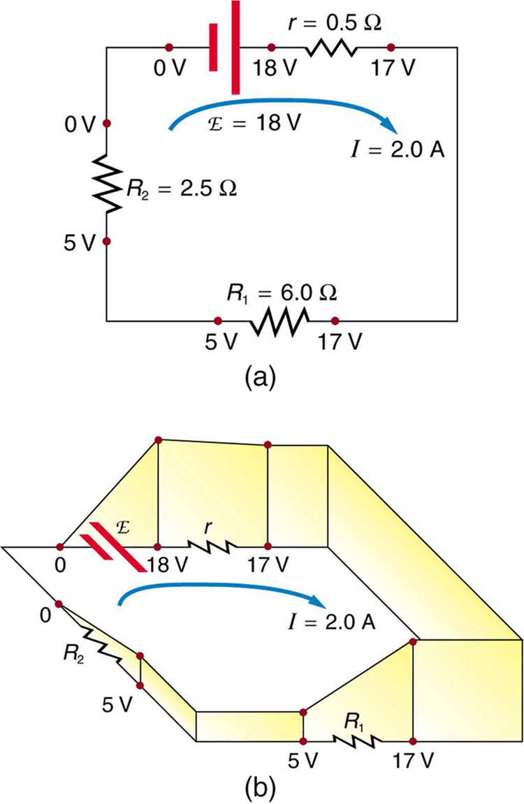
The loop rule. An example of Kirchhoff’s second rule where the sum of the changes in potential around a closed loop must be zero. (a) In this standard schematic of a simple series circuit, the emf supplies 18 V, which is reduced to zero by the resistances, with 1 V across the internal resistance, and 12 V and 5 V across the two load resistances, for a total of 18 V. (b) This perspective view represents the potential as something like a roller coaster, where charge is raised in potential by the emf and lowered by the resistances. (Note that the script E stands for emf.)
Applying kirchhoff’s rules
By applying Kirchhoff’s rules, we generate equations that allow us to find the unknowns in circuits. The unknowns may be currents, emfs, or resistances. Each time a rule is applied, an equation is produced. If there are as many independent equations as unknowns, then the problem can be solved. There are two decisions you must make when applying Kirchhoff’s rules. These decisions determine the signs of various quantities in the equations you obtain from applying the rules.
When applying Kirchhoff’s first rule, the junction rule, you must label the current in each branch and decide in what direction it is going. For example, in
[link] ,
[link] , and
[link] , currents are labeled
,
,
, and
, and arrows indicate their directions. There is no risk here, for if you choose the wrong direction, the current will be of the correct magnitude but negative.
When applying Kirchhoff’s second rule, the loop rule, you must identify a closed loop and decide in which direction to go around it, clockwise or counterclockwise. For example, in
[link] the loop was traversed in the same direction as the current (clockwise). Again, there is no risk; going around the circuit in the opposite direction reverses the sign of every term in the equation, which is like multiplying both sides of the equation by
[link] and the following points will help you get the plus or minus signs right when applying the loop rule. Note that the resistors and emfs are traversed by going from a to b. In many circuits, it will be necessary to construct more than one loop. In traversing each loop, one needs to be consistent for the sign of the change in potential. (See
[link] .)
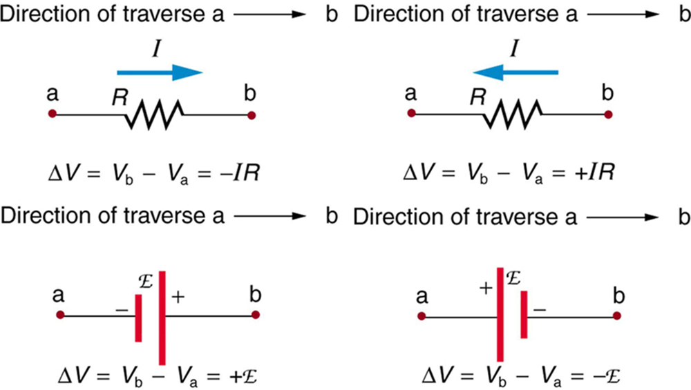
Each of these resistors and voltage sources is traversed from a to b. The potential changes are shown beneath each element and are explained in the text. (Note that the script E stands for emf.)
When a resistor is traversed in the same direction as the current, the change in potential is
. (See
[link] .)
When a resistor is traversed in the direction opposite to the current, the change in potential is
. (See
[link] .)
When an emf is traversed from
to + (the same direction it moves positive charge), the change in potential is +emf. (See
[link] .)
When an emf is traversed from + to
(opposite to the direction it moves positive charge), the change in potential is
emf. (See
[link] .)