

| << Chapter < Page | Chapter >> Page > |
Input/outputs and help
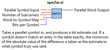
Above is the sub-VI we intend to build in this module. This is the first module where we've attempted to address the stochastic nature of our received data. We'll take each received symbol and compare it with our word-to-symbol map. The closest match is determined to be the most likely transmitted symbol.
The reason the incoming signals may not perfectly match our transmitted symbols is because realistically, computational artifacts from the FFT operation, noise, dispersive channels, quantization, and imperfect coherent carrier recovery are just a handful of the potential sources that can cause our data to change from the transmitter to the receiver.
Block diagram layout
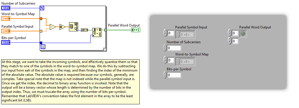
Above, Figure 2 shows a LabVIEW implementation of our slicer. As alluded to, we essentially compute minimum Euclidean distance between all allowed values of our symbols (from our known map) and our received data one subcarrier at a time. It's important to note indexing is enabled for our incoming data to perform our operation one data carrier at a time, but the word-to-symbol map is not, as we want to compare each incoming data symbol with all symbols in the map.
Once we take advantage of LabVIEW's max/min function, we desire only the index as this corresponds to the decimal equivalent of our binary word. Remember LabVIEW's convention that the first element in the output array corresponds to the least significant bit. Because the number of bits varies depending on the size of the map, the truncation shown at the end is necessary to remove excess leading zeros. For all general questions, check out the instructional video below in Figure 3, the example use video below in Figure 4, or email the author for more information.
Instructional video
Example video
Notification Switch
Would you like to follow the 'Fully configurable ofdm sdr transceiver in labview' conversation and receive update notifications?

|
|

|
|

|
|

|
|

|
|

|
|

|
|
|
|
|

|
|
|
|