

| << Chapter < Page | Chapter >> Page > |
Without the fiberglass body, and with the rear axle and drive shaft already removed, the removal of the engine and gearbox is quiet easy. In addition to the six main bell housing-to-engine bolts the Ford 2821E gearbox is held to the chassis by a mount bolted through the chassis ( [link] ). Despite partial melting of the rubber mount, this was readily unbolted ( [link] ). Removal of the starter motor is necessary prior to uncoupling the gearbox from the engine. Once all the bolts were removed, the gearbox is slid back off the input shaft, until it is free of the clutch and flywheel. It may then be lifted out of the chassis, and set aside for further inspection.


Prior to removal of the engine the intake manifold and remains of the fuel pump were detached. The upper housing of the Ford mechanical fuel pump had melted as a consequence of the fuel fire ( [link] ). The downdraft Weber 32DFM twin choke downdraught carburetor had melted during the fire ( [link] ) and become fused to the intake manifold ( [link] ). Removal of the intake manifold showed that the carburetor had actually melted and flowed through the manifold and into the intake ports on the head, resulting in etching of the head ( [link] ). This will be addressed during the engine rebuild. One of the intake manifold bolts was replaced to facilitate lifting the engine.


The exhaust system consists of two 2-into-1 manifolds ( [link] ) that join outside the chassis to a 2-into-1 collector that is part of the side pipe. Having removed the rear components of the exhaust ( [link] ) to facilitate the removal of the rear axle and suspension, the manifolds were removed ( [link] ) and a bolt was replaced to facilitate lifting the engine.


As with other Sevens, the engine in the Series 4 is held by two mounting brackets that are bolted via engine mounting rubbers, which are bolted to the chassis side rail with two bolts each ( [link] ). The engine mounting brackets ( [link] ) are bolted to the engine using four bolts per bracket. Once an engine hoist supported the Ford crossflow engine all of the mounting bolts were removed to allow the engine to swing free of the chassis ( [link] ).


The handbrake multiplying lever ( [link] ) was removed by unscrewing the two bolts through the chassis mounting bracket and the chassis. All other brackets and bolts were removed from the scuttle ( [link] ).


The Seven S4 chassis is actually comprised of a tubular structure reinforced by two sheet steel side panels that are spot welded along the side and underside of the chassis. Unfortunately, the passenger’s (right hand) side panel was significantly warped due to the melting of an ignition module that had been attached to it. In addition, there were signs of corrosion of the tubular chassis below the sheet panel ( [link] ), and it was decided to remove both panels and make new ones.

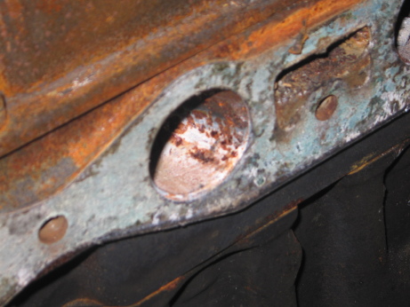
Using a wire brush to clean the surface rust revealed the position of each spot weld. Using a pilot point drill bit, each weld was drilled out allowing for the sheet to be removed. In most cases only a small dimple is formed in the chassis ( [link] ); however, in some cases the bit resulted in a small hole in the chassis rail. These will have to be repaired with the replacement of new side panels.

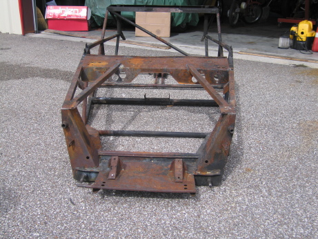
While the chassis was upside down to drill out the spot welds it was found that the lower front box section had corroded resulting in the destruction of a significant portion of the lower half ( [link] ). The two side panels are badly corroded ( [link] and [link] ) and will be replaced. [link] – [link] shows a range of views of the bare chassis.


Notification Switch
Would you like to follow the 'Lotus seven s4 (type 60): design, restoration, and maintenance' conversation and receive update notifications?

|
|

|
|

|
|

|
|

|
|

|
|

|
|
|
|
|
|
|
|
|