

| << Chapter < Page | Chapter >> Page > |
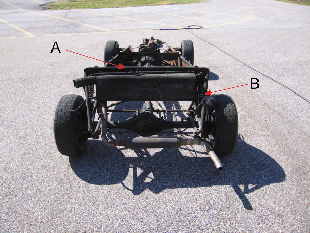
With the axle removed ( [link] ), the fuel tank may be lowered after removal of the two bolts at the side ( [link] B), and the fuel line. The two bolts at the top of the tank were removed when the body remains were detached ( [link] A). The tank shows some fire damage with removal of paint ( [link] ) and the destruction of the fuel gauge sender unit ( [link] ).


Removal of the wheels is followed by removal of the brake calipers ( [link] ) along with the brake hose so that the front suspension can be disassembled.

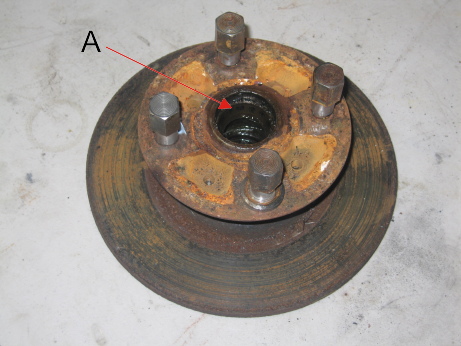
The bearing caps are removed by inserting a sharp pointed tool into the center hole and leveraging. Unfortunately, these required significant work since they had rusted in place. Under the cap, the retaining nut is held in place with a cotter pin. Removal of both of these allows the hub and bearings to be pulled off along with the brake disks. The disks were highly corroded ( [link] ) probably necessitating replacement. In contrast, the hubs can be reused once cleaned and with new bearings fitted. The disks are separated from the hubs by removing the four bolts.
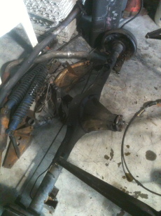
The uprights are readily removed by unbolting both the lower trunnion and the upper ball joints ( [link] ). The lower part of the shock absorber/spring unit ( [link] ) is not attached to the upright or trunnion but attached to the two lower wishbone halves by a separate bolt. Once this is removed the shock is free to move, as are the lower wishbones. Each of the lower wishbones is attached to a threaded pin welded to the lower part of the front box section. Due to the fire damage, the metalastic bushings on the right hand side had become welded to the pins. This meant that a propane torch was needed to heat the bushings sufficiently to remove from the chassis ( [link] ).


The steering rack was still functioning despite the rubber gaiters being destroyed. The rack clamp insulators were also badly fire damaged and crumbled while being removed. Three of the four bolts holding the two rack clamps were readily loosened; however, the last (forward passenger side) sheered-off ( [link] ) and will have to be drilled out.

Notification Switch
Would you like to follow the 'Lotus seven s4 (type 60): design, restoration, and maintenance' conversation and receive update notifications?

|
|

|
|

|
|
|
|
|

|
|
|
|

|
|

|
|

|
|

|