

| << Chapter < Page | Chapter >> Page > |
__no_operation() instructs the MSP430 to do nothing
during one cycle; by repeating this many times, time can bemeasured. As this is neither accurate nor energy-efficient, a
more elegant technique will be shown in
section 3.4 .
source_code/iar_v4.11/lab_ezwsn.eww with IAR. The project corresponding to this section is called
led_loop . .#include "io430.h"
#include "in430.h"int main( void )
{WDTCTL = WDTPW + WDTHOLD;
int i;P1DIR |= 0x03;
while (1) {P1OUT ^= 0x03;
for (i=0;i<10000;i++) {
__no_operation();}
}}
Blinking LEDs using an active waiting loop
Some keys for understanding the code:
^= causes 1s to become 0s and vice-versa (aka toggling).In case of our LEDs, it causes their on/off state to change;__no_operation(); causes the MSP430 to do nothing for one cycle.We want to measure time precisely with the oscilloscope. This can, in theory, be done by measuring the voltage at the LEDs, but it is hard to hold the probes right. We will therefore use extension pin
P6 represented in the figure below, which is connected to
P2.3 on the MSP430.
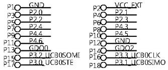
We will configure
P2.3 to be output and toggle its state together with the state of the LEDs. Therefore:
P2DIR |= 0x08; after line 7 to declare
P2.3 as output;P2OUT ^= 0x08; after line 9 to toggle
P2.3 after toggling the LEDs;P6 , ground on extension
port
P12 ;threshold value for
i |
measured toggle duration |
| 1000 | 6.72ms |
| 10000 | 67.2ms |
| 20000 | 134.0ms |
| 30000 | 201.0ms |
Notification Switch
Would you like to follow the 'Ezwsn: experimenting with wireless sensor networks using the ez430-rf2500' conversation and receive update notifications?

|
|

|
|

|
|

|
|

|
|

|
|

|
|

|
|

|
|
|
|