

| << Chapter < Page | Chapter >> Page > |
The resulting energy levels are shown in [link] .
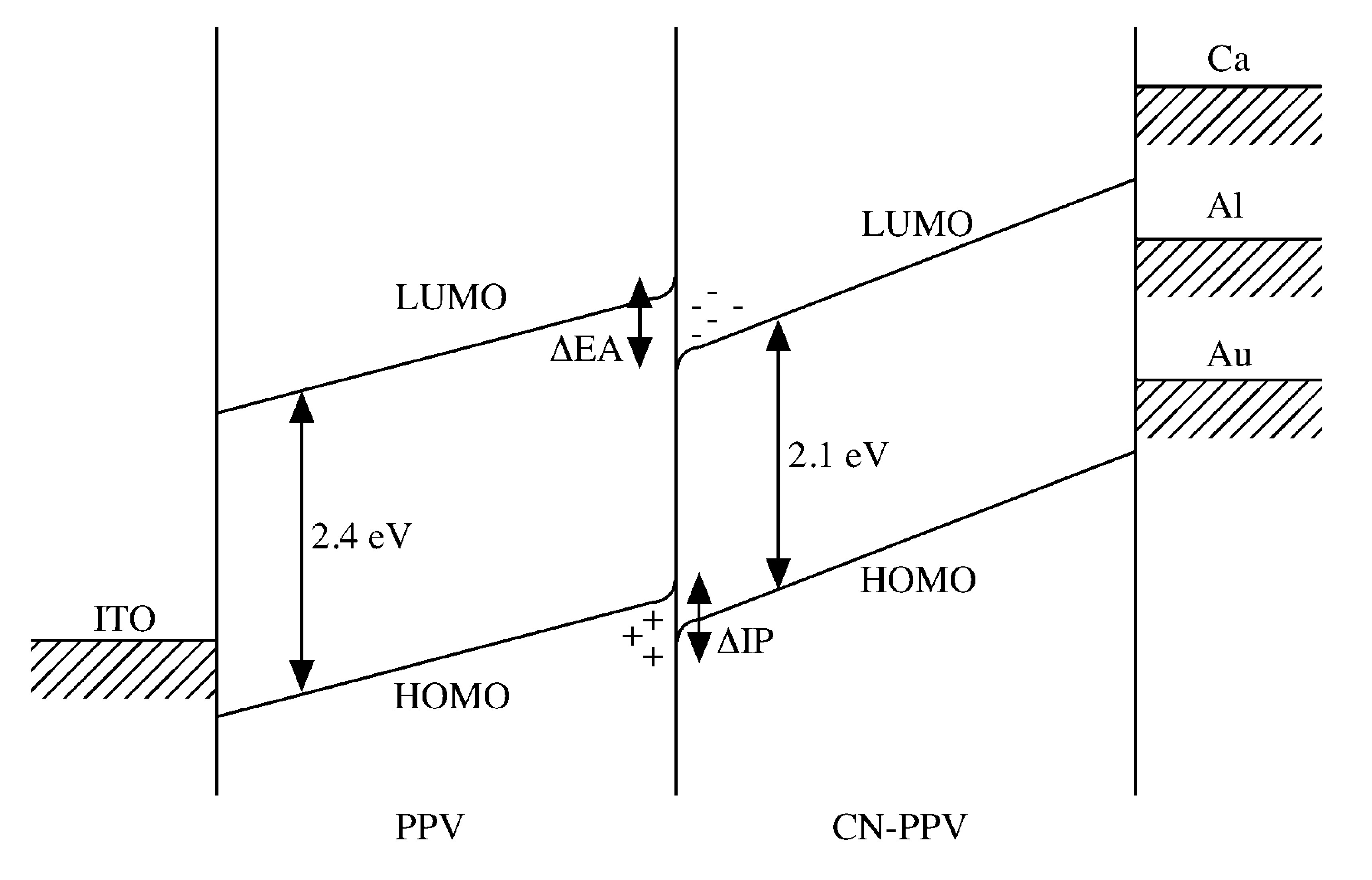
The absolute energies of levels are not known accurately, but the diagram show the relative position of the HOMO and LUMO levels in the polymers, and the Fermi levels of the various possible metal contacts, the differences in electron affinity (ΔEA) and ionization potential (ΔIP) between PPV and CN-PPV are also shown ( [link] ).
At the polymers interface there is a sizable offset in the energies of HOMO and LUMO of PPV and CN-PPV, the holes transported from the ITO and the electrons transport from the aluminum will be confined in the heterojunction. The local charge density will be sufficiently high to ensure the holes and electrons will pass within a collision capture radius. This set-up increases the chance for an electrons to combine with holes to form an excition. In addition, the emission will be close to the junction, far away from the electrode junction which will quench the singlet excitions. The result is that a multi-layers LED has an internal quantum efficiency of 10% and external quantum efficiency (for light emitted in foreword direction) of 25%.
Based on this approach, a couple of polymers have been developed or modified to produce the desirable emission color and processing property. The drawback of this method is that desirable properties may not be commentary to each other. For example, in MEH-PPV an alkoxy side group (RO) is introduced to PPV so that it can be dissolved in organic solvent. But the undesirable effect is that MEH-PPV is less thermally stable. Moreover in multiple layers LEDs, different polymer layers have different refractive indices and a fraction of the photons will undergo total internal reflection at the refractive boundaries and cannot escape as light. This problem can be overcome by Febry-Pert microcavity structure.
Fabry-Perot resonant structures are also used in inorganic LED, and are is based on Fermi’s golden rule:
K r ∼ |<M>| r (v)
where M (the matrix element of the perturbation between final and initial states) depends on the nature of the material, and r (v) can be altered by changing the density of various density states, e.g. using a luminescent thin films to select certain value of V.
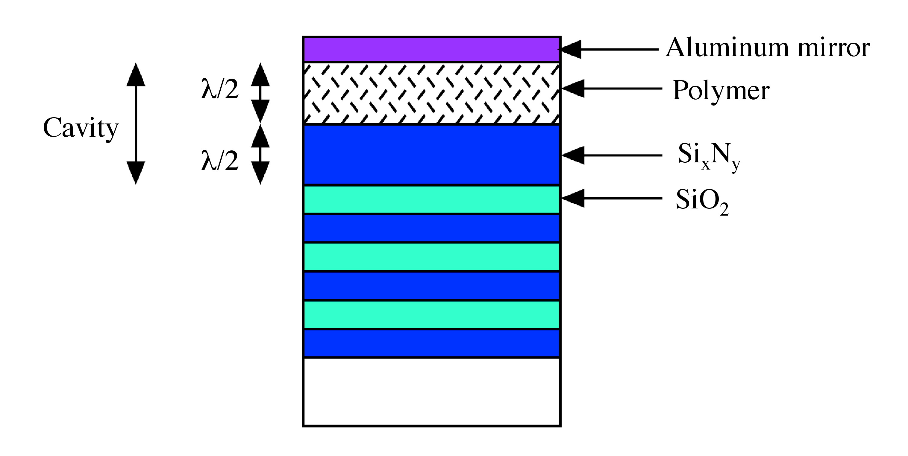
In building a microcavity for a polymer LED, the polymer is placed between two mirrors. ( [link] ), in which one of the mirrors is made up of aluminum, the other mirror (a Bragg Mirror) is form by epitaxial multilayer stacks of Si x N y and SiO 2 .
Doping is a process that creates carrier by purposely introducing impurities and is very popular method in the semiconductor industry. However, this technique was not used in polymer LED until 1995, when a co-polymer polystyrene-poly(3-hexylthiphene) (PS-P3HT) was doped with FeCl 3 . Doping of MEH-PPV with iodine has improved the efficiency by 200% and the polymer LED can be operated under both forward and reverse bias ( [link] ). The doping is accomplsihed by mixing 1 wt% MEH-PPV with 0.2 wt% I 2 . The molar ratio of MEH-PPV to I 2 is 5:1. That is a huge “doping “ ratio when you compare the doping concentration in the semiconductor.
Notification Switch
Would you like to follow the 'Chemistry of electronic materials' conversation and receive update notifications?

|
|

|
|

|
|

|
|

|
|

|
|

|
|
|
|
|

|
|

|