

| << Chapter < Page | Chapter >> Page > |
void process(Int16 *r_data, Int16 *w_data
{/* Processing functions (user-defined) */
}
In this section we will describe the way the driver is used in the CCS environment.
An example of this process is provided in the next section.
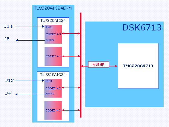
The example creates two audio paths as follows:
Path # 1: J14 ⇒ CODEC#0/INP1 ⇒ SMARTDM/Channel 0 ⇒ McBSP1/Channel 0 ⇒ DSP ⇒ McBSP1/Channel 2 ⇒ SMARTDM/Channel 2 ⇒ CODEC#2/OUTP1 ⇒ J4
Path # 2: J13 ⇒ CODEC#2/INP3 ⇒ SMARTDM/Channel 2 ⇒ McBSP1/Channel 2 ⇒ DSP ⇒ McBSP1/Channel 0 ⇒ SMARTDM/Channel 0 ⇒ CODEC#0/OUTP2 ⇒ J5
The example is illustrated in Figure 9. A user defined function “test.c” was created for this application.
The first part of the program defines the buffers for reading and writing samples.
#define NUM_CODECS	4	// The number of CODECs connected
#define DATANUM	128	// The number of samples  in each channel#define DATAMODE	0	// AIC24 operates in data mode

#if 〔DATAMODE == 1〕#define BUFS_PER_CHANNEL 1
#else#define BUFS_PER_CHANNEL 2
#endifInt16 r_data1[DATANUM*NUM_CODECS*BUFS_PER_CHANNEL];  // data buffer for readInt16 w_data1[DATANUM*NUM_CODECS*BUFS_PER_CHANNEL];    // data buffer for readInt16 r_data2[DATANUM*NUM_CODECS*BUFS_PER_CHANNEL];    // data buffer for writeInt16 w_data2[DATANUM*NUM_CODECS*BUFS_PER_CHANNEL];    // data buffer for write
The callback function follows the template introduced in the previous section, and calls the subroutine “copyData”.
void copyData〔Int16 *inbuf, Int16 *outbuf, Int16 length〕
{Int16 i = 0;for 〔i = 0; i<length; i++rbbrk; {
        outbuf[i]= inbuf[i];}
}// The callback function that is called when the EDMA buffers are full
// The function copies the data from channel 0 to channel 2void process(Int16 *r_data, Int16 *w_data)
{if (hAIC24.DataMode)
	{int i;
		for (i=0; i<DATANUM; i++)
			r_data[0*DATANUM+i]⩓= 0xfffe;
	}copyData(r_data+0*DATANUM, w_data+2*DATANUM, DATANUM);
}
The main program:
After this step, the program will enter in an endless loop. Samples will be processed each time an EDMA interrupt occurs.
int main()
{// setting up the AIC24 handle
	AIC24_InitDefaults(⩓hAIC24, NUM_CODECS, DATANUM, r_data1, r_data2, w_data1, w_data2, process);// determining data mode (continuous or programming)
	hAIC24.DataMode = DATAMODE;// example for setting devices input and outputs
	// if defaults are ok then this is not necessaryhAIC24.Regs[0].creg6.reg6a.control_bit.mici = 0;hAIC24.Regs[0].creg6.reg6a.control_bit.inp1 = 1;hAIC24.Regs[0].creg6.reg6a.control_bit.inp2 = 0;hAIC24.Regs[0].creg6.reg6a.control_bit.inp3 = 0;hAIC24.Regs[0].creg6.reg6a.control_bit.inp4 = 0;hAIC24.Regs[0].creg6.reg6b.control_bit.outp1 = 0;hAIC24.Regs[0].creg6.reg6b.control_bit.outp2 = 1;hAIC24.Regs[0].creg6.reg6b.control_bit.outp3 = 0;hAIC24.Regs[1].creg6.reg6a.control_bit.mici = 0;hAIC24.Regs[1].creg6.reg6a.control_bit.inp1 = 0;hAIC24.Regs[1].creg6.reg6a.control_bit.inp2 = 0;hAIC24.Regs[1].creg6.reg6a.control_bit.inp3 = 0;hAIC24.Regs[1].creg6.reg6a.control_bit.inp4 = 0;hAIC24.Regs[1].creg6.reg6b.control_bit.outp1 = 0;hAIC24.Regs[1].creg6.reg6b.control_bit.outp2 = 0;hAIC24.Regs[1].creg6.reg6b.control_bit.outp3 = 0;hAIC24.Regs[2].creg6.reg6a.control_bit.mici = 0;hAIC24.Regs[2].creg6.reg6a.control_bit.inp1 = 0;hAIC24.Regs[2].creg6.reg6a.control_bit.inp2 = 0;hAIC24.Regs[2].creg6.reg6a.control_bit.inp3 = 1;hAIC24.Regs[2].creg6.reg6a.control_bit.inp4 = 0;hAIC24.Regs[2].creg6.reg6b.control_bit.outp1 = 1;hAIC24.Regs[2].creg6.reg6b.control_bit.outp2 = 0;hAIC24.Regs[2].creg6.reg6b.control_bit.outp3 = 0;hAIC24.Regs[3].creg6.reg6a.control_bit.mici = 0;hAIC24.Regs[3].creg6.reg6a.control_bit.inp1 = 0;hAIC24.Regs[3].creg6.reg6a.control_bit.inp2 = 0;hAIC24.Regs[3].creg6.reg6a.control_bit.inp3 = 0;hAIC24.Regs[3].creg6.reg6a.control_bit.inp4 = 0;hAIC24.Regs[3].creg6.reg6b.control_bit.outp1 = 0;hAIC24.Regs[3].creg6.reg6b.control_bit.outp2 = 0;hAIC24.Regs[3].creg6.reg6b.control_bit.outp3 = 0;// Starting the AIC24
	AIC24_Start(⩓hAIC24);
Notification Switch
Would you like to follow the 'From matlab and simulink to real-time with ti dsp's' conversation and receive update notifications?

|
|

|
|

|
|

|
|

|
|

|
|

|
|
|
|
|

|
|

|